Difference between revisions of "LinkNode Buzzer Module"
(Created page with "== Introduction == The Buzzer module has a piezo buzzer as the main component. It can be connected to an analog pulse-width modulation output to generate various tones and ef...") |
(No difference)
|
Latest revision as of 02:22, 13 December 2016
Introduction
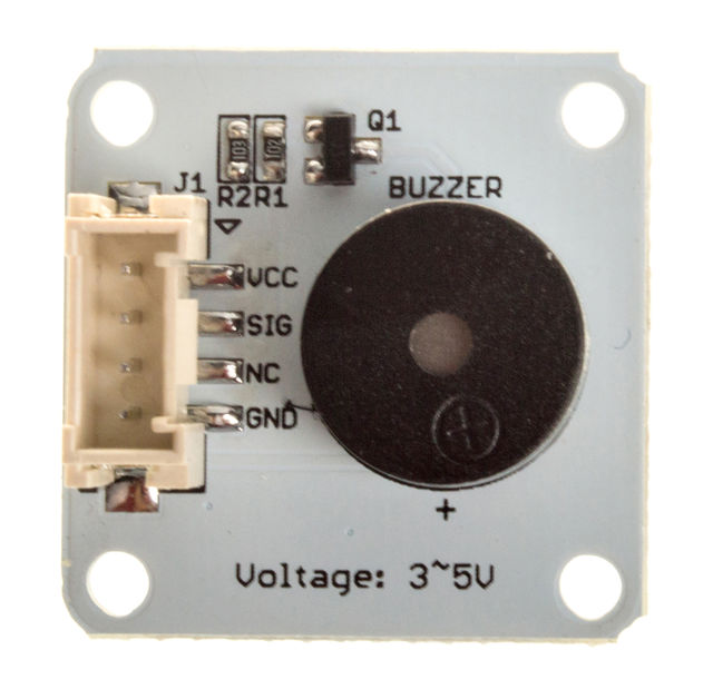
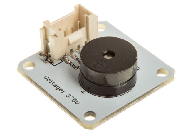
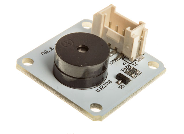
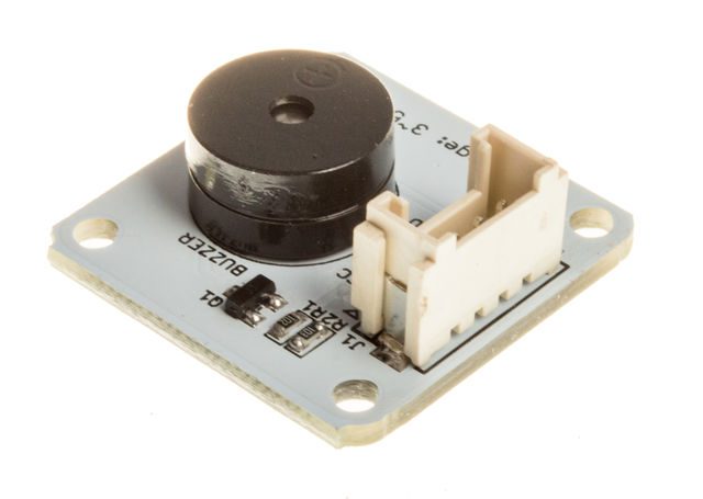
The Buzzer module has a piezo buzzer as the main component. It can be connected to an analog pulse-width modulation output to generate various tones and effects.
Wiring & Running
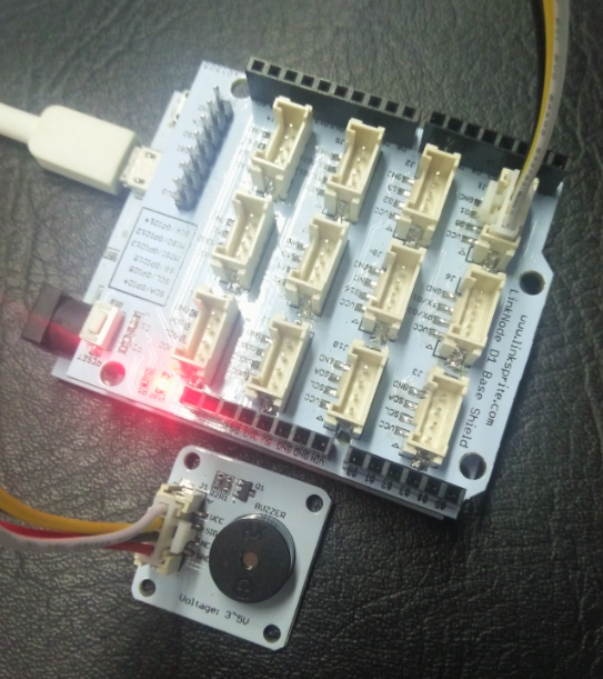
The module is connected to the base shield J1:
Buzzer Signal --> LinkNode D1 G0
Power on and download the simple code, we can hear a ticking sound coming from the buzzer.
Simple Code
const int beep_pin = 0;

void setup() {
  // put your setup code here, to run once:
  pinMode(beep_pin,OUTPUT);
}

void loop() {
  // put your main code here, to run repeatedly:
  unsigned int hz = 1800;
  unsigned int time_ms = 800;
  buzzer(hz,time_ms);
  delay(1500);
}
void buzzer (int hz,int time)
{
  if(hz <= 500)
  {
    for(int i = 0; i < (time/(1000/hz)); i ++)
    {
      digitalWrite(beep_pin,HIGH);
      delay(500/hz);
      digitalWrite(beep_pin,LOW);
      delay(500/hz);
    }
  }
  else
  {
    for(int i = 0; i < ((time*1000)/(1000000/hz)); i ++)
    {
      digitalWrite(beep_pin,HIGH);
      delayMicroseconds(500000/hz);
      digitalWrite(beep_pin,LOW);
      delayMicroseconds(500000/hz);
    }
  }
}
