Difference between revisions of "LinkNode R4: Arduino-compatible WiFi relay controller"
| (3 intermediate revisions by the same user not shown) | |||
| Line 14: | Line 14: | ||
| − | + | == Product UPC == | |
| − | + | Product UPC: 713382671484 | |
== Features == | == Features == | ||
| Line 81: | Line 81: | ||
'''5.Configure to accece WiFi AP''' | '''5.Configure to accece WiFi AP''' | ||
| − | *Supply the power for LinkNodeR4, the LinkNode R4 will create a AP called '''LinkNodeAP''' | + | *Supply the power for LinkNodeR4, the LinkNode R4 will create a AP called '''LinkNodeAP'''. If it can't be detected, switch off your wifi router and try again. |
*Use your mobile phone to connect this AP | *Use your mobile phone to connect this AP | ||
| Line 327: | Line 327: | ||
[[File:LinkNode_R4b.png]] | [[File:LinkNode_R4b.png]] | ||
| − | [https://s3.amazonaws.com/cutedigi/linknode+r4/LinkNode+R4a. | + | [https://s3.amazonaws.com/cutedigi/linknode+r4/LinkNode+R4a.STL Linknode R4 3D Builder a] |
[https://s3.amazonaws.com/cutedigi/linknode+r4/LinkNode+R4b.stl Linknode R4 3D Builder b] | [https://s3.amazonaws.com/cutedigi/linknode+r4/LinkNode+R4b.stl Linknode R4 3D Builder b] | ||
Latest revision as of 05:52, 20 June 2017
Contents
Introduction
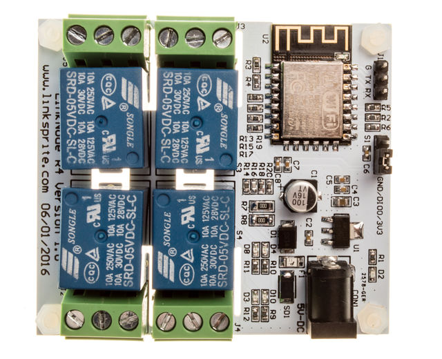
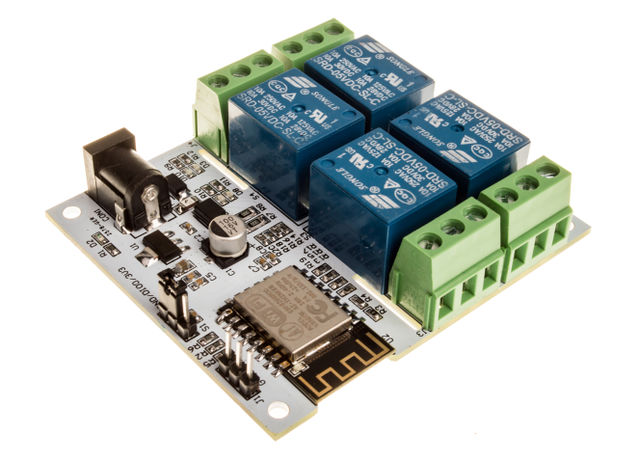
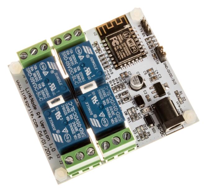
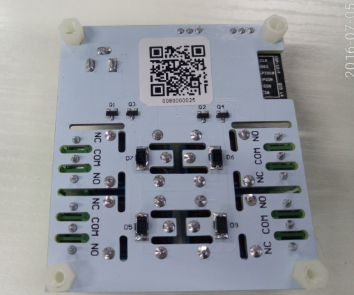
LinkNode R4 is a WiFi relay controller and it is powered by ESP-12f ESP8266 WiFi module which is comptiable with Arduino programming. There are 4 relay channels and each channel allows you to control high-power devices (up to 10 A) via the on-board relay. LinkNode R4 can be used to remotely turn lights, fans and other devices on/off. The WiFi interface will allow you to associate the board with your existing WiFi network and send the commands over the network.
Product UPC
Product UPC: 713382671484
Features
- ESP-12f ESP8266 WiFi module
- 4 Channel relays,supporting:
- 277V AC, 10A
- 125V AC, 12A
- 5V DC power
- Two work modes:
- Program via UART
- Boot from flash
- 4 indiator LEDs
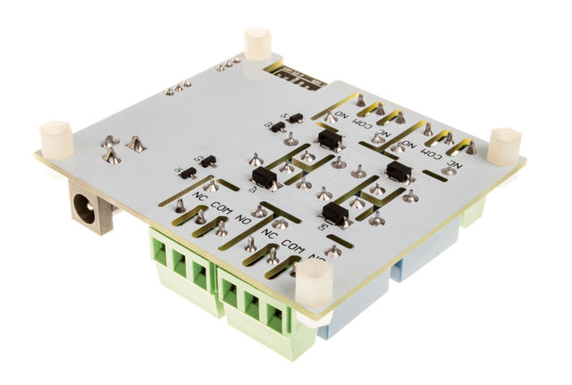
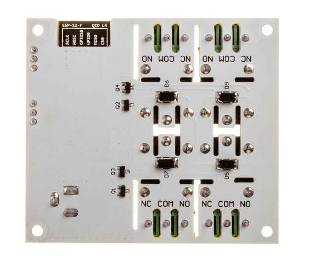
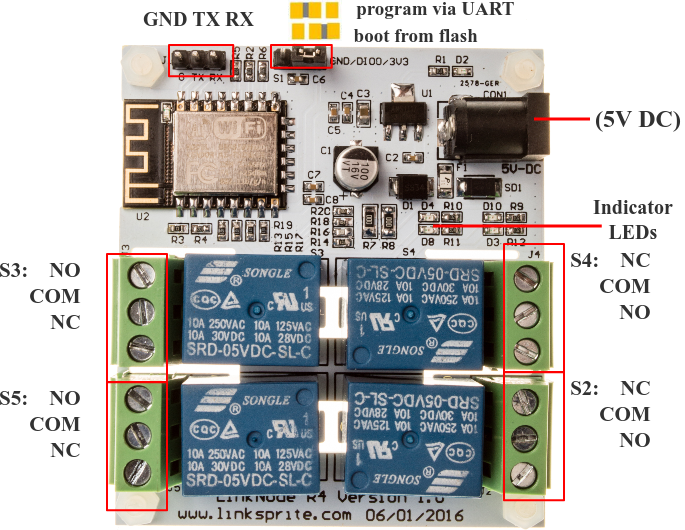
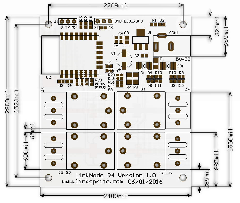
LinkNode R4 Diagram
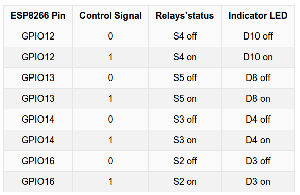
Control logic
How to use Android APP to control LinkNode R4
LinkNode R4 is an open source 4-Channel relay controller which is powered by the ESP8266 WiFi SoC.
The following will introduce how to use Android APP to control the LinkNode R4.
Steps
1. Install Android and iOS APP
- Download the APK file from the LinkNode-Rx-2016-12.apk and install it.
- if your equipment is iphone/ipad,you can get the app form appstore and name is "LinkNode Relay".
- iOS App download link :LinkNode Relay
2.Login LinkSpriteIO
- If you never register an account on LinkSpriteIO, please enter Email and your password, then click the REGISTER button
- If you have an account on LinkSpriteIO, please enter Email and your password, then click the SIGN IN button
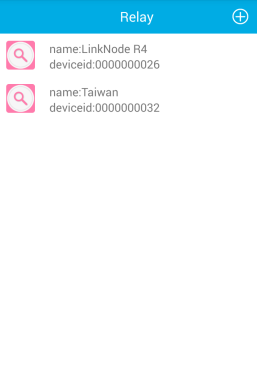
3. Go to Relay device list
- Click the plus icon on the upper right quarter to add a new LinkNode R4.
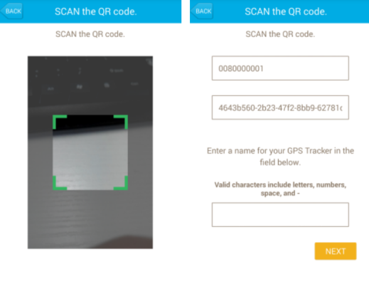
4.Scan the QRcode
- Get the device information and register it to your account.
5.Configure to accece WiFi AP
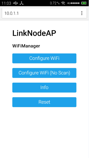
- Supply the power for LinkNodeR4, the LinkNode R4 will create a AP called LinkNodeAP. If it can't be detected, switch off your wifi router and try again.
- Use your mobile phone to connect this AP
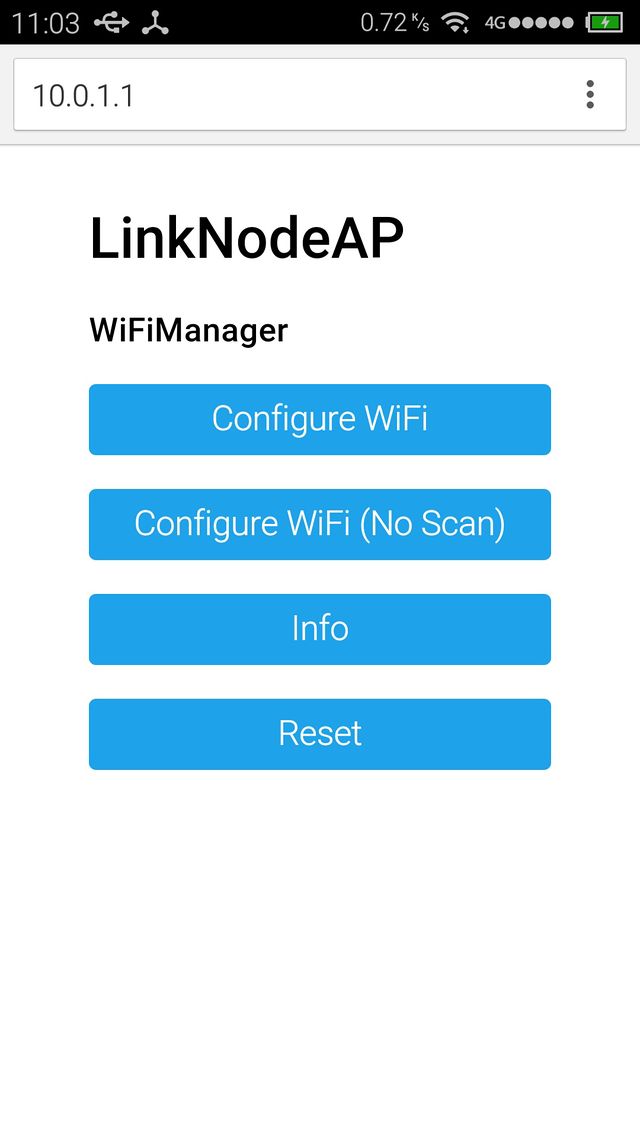
- Open a browser and enter the ip address 10.0.1.1 and you will see the following website:
- Click the button configure WiFi
- Select your WiFi AP which you want to connect and enter your wifi password.
- If connecting failed, you can go to the same website to configure it again.
- After that, LinkNode R4 will connect to Linksprite IO via the internet.
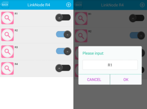
6.Control your 4-channel relay
- control the button on the right side to turn on or off the relays, and you can click the relay's name to change it.
Tutorial
1. Get started in Arduino programming
a. Requirements
Software
- Arduino IDE, (the latest version is 1.6.8 )
- The Arduino core for LinkNode R4
** Hardware**
- 5V/1A DC power is recommanded.
- USB TTL UART cable
b. Install Arduino core for ESP8266
- Install Arduino 1.6.8 from the Arduino website.
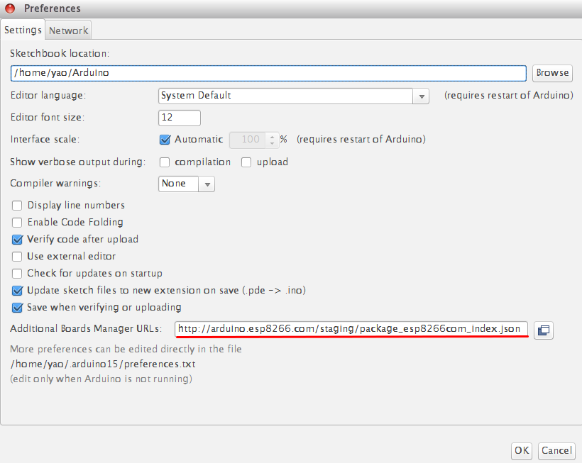
- Start Arduino and go to File --> Preferences .
- Enter http://arduino.esp8266.com/stable/package_esp8266com_index.json into Additional Board Manager URLs field. You can add multiple URLs, separating them with commas.
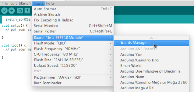
- Open Boards Manager from Tools --> Board menu --> Boards Manager.
- Search and install esp8266 platform (and don't forget to select your ESP8266 board from Tools --> Board menu after installation).
c. Check the configuration of Board
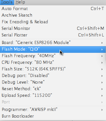
Because the LinkNode R4 has not been added into the offcial ESP8266 Arduino core repository yet, so you can't find this board on the boards list, but you can use the Generic ESP8266 Module, and select Flash Mode as QIO.
d. Create a Arduino Project
- Enter the following source code and compile
 /*Turn on and off the S3 relay in every second */
 void setup()
 {
   pinMode(12,OUTPUT);
   Serial.begin(9600);
 }
 void loop()
 {
   digitalWrite(12,HIGH);
   Serial.println("Relay ON\n");
   delay(1000);
   digitalWrite(12,LOW);
   Serial.println("Relay OFF\n");
   delay(1000);
 }
e. Test
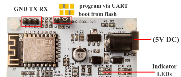
- Jump out the S5 on LinkNode R4 and select program via UART
- Connect DC power to LinkNode R4
- Connect USB TTL UART cable to UART port of LinkNode R4
- Connnect the other side to PC
- Check your serial port which your PC recognize
- Click the **Upload* on Arduino IDE
- After finished, jump out the S5 on LinkNode R4 and select boot from flash
2. Remotely control LinkNode R4 with LinkSprite.IO platform
LinkSprite IO is an IoT platform which supports RESTful API and WebSocket. These make the mobile APP, website application or device connect it very easily. The following I will introduce is about how to use LinkNode R4 to communicate with LinkSprite IO platform.
a. Create a new account and device on LinkSprite.io
Go to www.linksprite.io and sign up Enter your Email and password to create a new account Go to My Account to get your own API Key. The API Key is fatal because only add the Key in your codes, can the data sync to your IoTgo account.
- Click My Device, and choose Create DIY Device.
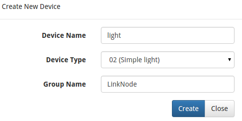
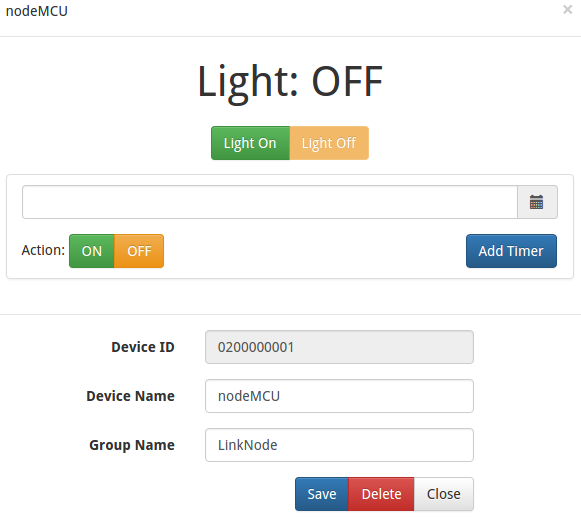
- Click the created device icon and get the DeviceID.
b. Query the source code using your own apikey and device ID
Device API which the LinkSprite IO support is JSON-based, which means all request and response data is enclosed in JSON format. Currently it supports 3 kind of request.
- Update: Update device status to LinkSprite IO
- Query: Get device status from LinkSprite IO
This demo will send http POST request to query the param--light on linksprite.io, if the light is on, then turn one relay on, if off, then turn off the relay.
c. Install WiFi Manager library
To make it more convinent, we add WiFi manager library in this demo.
The ESP8266 WiFi Connection manager with web captive portal, this Arduino library can make configure AP's SSID and password via web page when you want LinkNode R4 to connect to AP.
- Open Arduino IDE and go to Sketch --> Include Library --> Manage Libraries
- Search the wifimanager and install it
d. Develope source code
- Enter the following source code
- Configure your apikey and deviceID in the source code
   #include <ESP8266WiFi.h>
   #include <WString.h>
   //the library are needed for autoconfig WiFi
   #include <DNSServer.h>
   #include <ESP8266WebServer.h>
   #include <WiFiManager.h>
   // replace with your own API key and device ID,
   String apikey = "xxxxxxxxxxxxxxxxxxxxxxxxxxxx";
   const char* deviceID="xxxxxxxxxxxxx";
  const char* server = "www.linksprite.io";
 WiFiClient client;
 void setup() {
   Serial.begin(115200);
   pinMode(12, OUTPUT);
   WiFiManager wifiManager;
   wifiManager.setAPStaticIPConfig(IPAddress(10,0,1,1), IPAddress(10,0,1,1), IPAddress(255,255,255,0));
   wifiManager.autoConnect("LinkNodeAP");
   Serial.print("WiFi Connected ...\n");
   Serial.println("WiFi connected");
 }
 void loop() {
   if (client.connect(server,80)) {
   String  postStr ="{";
           postStr +="\"action\":\"query\",";
           postStr +="\"apikey\":\"";
           postStr += apikey;
           postStr +="\",";
           postStr +="\"deviceid\":\"";
           postStr += deviceID;
           postStr +="\",";
           postStr += "\"params\":";
           postStr += "[";
           postStr += "\"light\"";
           postStr +="]";
           postStr +="}";
      client.print("POST /api/http HTTP/1.1\n");
      client.print("Host: ");
      client.print(server);
      client.print("\nContent-Type: application/json\n");
      client.print("Content-Length: ");
      client.print(postStr.length());
      client.print("\n\n");
      client.print(postStr);
   }
   delay(1000);
   Serial.println("Store response...");
   String request = "";
   while (client.available()) {
     char c = client.read();
     request +=c;
   }
 if (request!= NULL)
 {
   int index1 = request.indexOf(":{");
   int index2 = request.indexOf("},");
   String param = request.substring(index1, index2 + 1);
   Serial.print("The param is ");
   Serial.println(param);
   if(param.indexOf("off")>0){
       digitalWrite(12, LOW);
       Serial.println("OFF");
   } else if(param.indexOf("on")>0){
       digitalWrite(12, HIGH);
       Serial.println("ON");
   }
 client.stop();
 Serial.println("Waiting...");
 delay(2000);
 }
 }
e. Configure to accece WiFi AP
- Take the step above to upload the program, the LinkNode R4 will create a AP called LinkNodeAP
- Use your mobile phone to connect this AP
- Open a browser and enter the ip address 10.0.1.1 and you will see the following website:
- Click the button configure WiFi
- Select your WiFi AP which you want to connect and enter your wifi password.
- If connecting failed, you can go to the same website to configure it again.
- Also, you can use Serial Monitor in Arduino IDE to check the status.
- After that, LinkNode R4 will connect to Linksprite IO via the internet.
f. Test
- Open the serial monitor to check the status
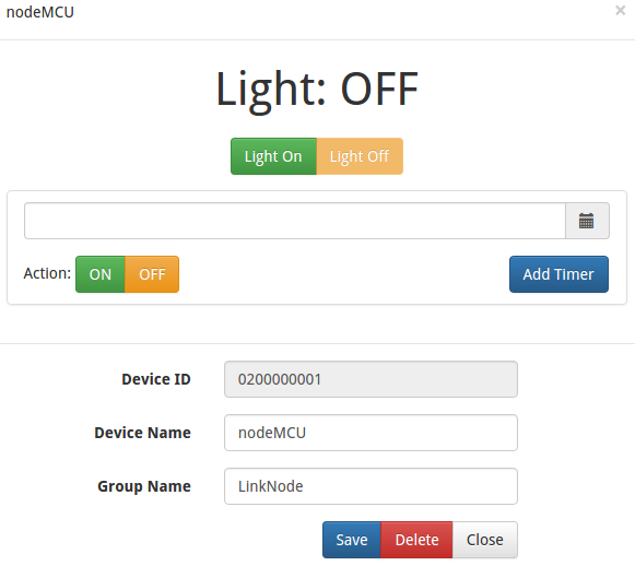
- Open your light device which is create on linksprite.io
- Click the button ON and OFF
- Check the status of relay on LinkNode R4, is it following your control?
