Difference between revisions of "Cube Solver Robot with Arduino"
(→2.Hardware List) |
|||
| (3 intermediate revisions by the same user not shown) | |||
| Line 21: | Line 21: | ||
== 2.Hardware List == | == 2.Hardware List == | ||
| − | + | ||
*1x Power Base Shield | *1x Power Base Shield | ||
| − | |||
| − | |||
*4x Servo | *4x Servo | ||
| Line 51: | Line 49: | ||
* 26x Inner Hexangular M3*12mm | * 26x Inner Hexangular M3*12mm | ||
| − | * 2x Inner Hexangular M3* | + | * 2x Inner Hexangular M3*16mm |
* 4x Inner Hexangular M4*25mm | * 4x Inner Hexangular M4*25mm | ||
| Line 284: | Line 282: | ||
= Video = | = Video = | ||
[https://www.youtube.com/watch?v=_MEE6EA79wM&t=121s LinkSprite Magic Cube Assemble] | [https://www.youtube.com/watch?v=_MEE6EA79wM&t=121s LinkSprite Magic Cube Assemble] | ||
| + | |||
[https://www.youtube.com/watch?v=UKLXMJf-2-8 LinkSprite Magic Cube Working] | [https://www.youtube.com/watch?v=UKLXMJf-2-8 LinkSprite Magic Cube Working] | ||
Latest revision as of 06:42, 31 July 2017
Contents
Introduction
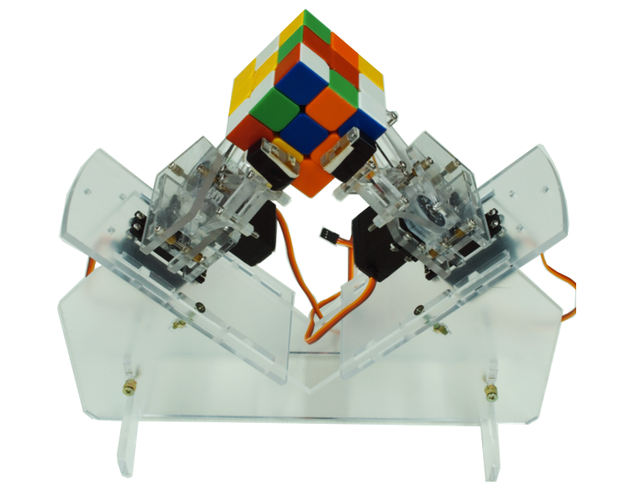
This product is a cube solver robot with Arduino. At present,there are 3 actions including 90 degrees clockwise rotation, 90° anticlockwise rotation and 180 degrees rotation. The robot executes the corresponding action depending on the Rubik's cube reduction formula to solve the cube.
The type of cube which the Robot can solve is Standard third-order cube(Flexible rotating cube will be more better) The size of cube: International standard Rubik's Cube (57*57*57mm)
Assembly instructions
1.Mechanical assembly
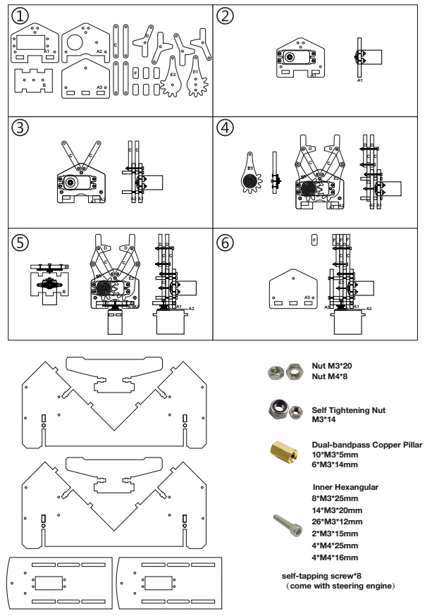
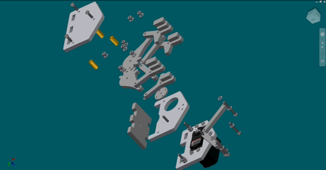
Assembly diagram
2.Hardware List
- 1x Power Base Shield
- 4x Servo
- 2x Acrylic Mechanical Arm
- 1x Acrylic Base Plate
- Screw And Nut
- 20x Nut M3
- 8x Nut M4
- 14x Self Tightening Nut
- 10x Dual-bandpass Copper Pillar M3*5MM
- 6x Dual-bandpass Copper Pillar M3*14MM
- 8x Inner Hexangular M3*25mm
- 14x Inner Hexangular M3*20mm
- 26x Inner Hexangular M3*12mm
- 2x Inner Hexangular M3*16mm
- 4x Inner Hexangular M4*25mm
- 4x Inner Hexangular M4*16mm
- 1x Power Adapter(5V/3A 5.5*2.5mm )
- 1x Packing Box
3.Installation steps
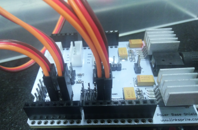
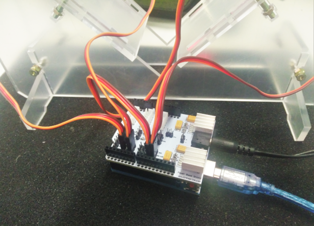
3.1 Insert the power base shield in the Arduino Uno
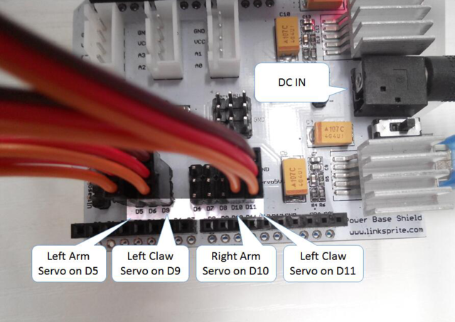
3.2 Connect the servos of left arm , left paw , right arm , right paw to D5,D9,D10,D11.
3.3 Connect external power supply to power base shield. note: enhance the heat dissipation of regulator IC on power base shield (Install heat sink or cooling fan)
3.4 Connect Arduino to computer with usb cable.
Note: Voltage of external power supply should be 6-12v, Output current should be greater than 2.5A, The lower voltage of power supply, the less heat of regulator IC on power base shield.
Software Installation
Cube Explorer
The software can calculate solution of a cube within several seconds .
1.Download the latest version of Cube Explorer from https://s3.amazonaws.com/linksprite/Cube+Robot/CubeExplorer.7z , Extract the software to any folder to complete the installation.
2.Double-click cubeXXXhtm.exe to start the software (XXX is the version number of the software).
Arduino Program
1. Go go Arduino IDE libraries and open libraries/Servo/src/avr/Servo.cpp
2.Comments out 283 to 280 lines in the code , in order to more accurately correct the angle of steering, if the steering gear should be used in other program, you need to change the code back.
if( value < SERVO_MIN() )
value = SERVO_MIN();
else if( value > SERVO_MAX() )
value = SERVO_MAX();
3. Open MyCube.ino to compile and download to Arduino Uno
Debugging
Debug Left Arm And Right Arm
Take the left arm as an example:
Uncomment the line 82 in the code, compile and download the program. Now the left arm will spin at 0 degrees, 90 degrees, 180 degrees. Adjust the value of the three macro definition(LEFT_ARM_0、LEFT_ARM_90、LEFT_ARM_180) at the 16-18 lines in the program, to let the left arm just stop at 0 degrees , 90 degrees and 180 degrees.
The formula of the value as follow:
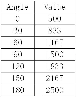
Result = angle * (100 / 9) + 500
Common angle values as following table:
Please comment this line of code again after debugging.
The debugging method of right is the same as left arm.
Debug Left Paw And Right Paw
Take the left paw as an example:
Uncomment the line 82 in the code, compile and download the program. Now the left claw will repeat these actions of open, clutch, release. Adjust the value of the three macro definition(LEFT_ARM_0、LEFT_ARM_90、LEFT_ARM_180) at the 9-11 lines of program, then it will not affect the rotation of the cube when open the left paw , the cube will not fall when it is grasped by the paw, and the aw will hold on the cube when it release the cube. You can easily place or take the cube
Please comment this line of code again after debugging.
The debugging method of right is the same as left paw.
Operation Instructions
Cube Explorer Use Guide
Download the latest version of the Cube Explorer or use the Cube Explorer what we offered, unzip Cube Explorer to any folder to complete the installation . Double-click the Start software of cubeXXXhtm.exe (XXX is the version number of the software) . Initial start-up will need several minutes to calculate and generate some spreadsheet file and stored in the current directory . When you start the program again, the program will read these files directly without any extract calculation.
Cube Explorer replace or generate files only in their own folder. So when you uninstall Cube Explorer, delete the entire folder.
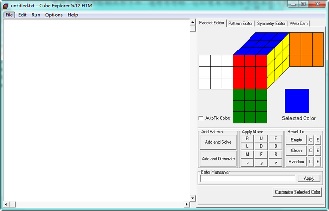
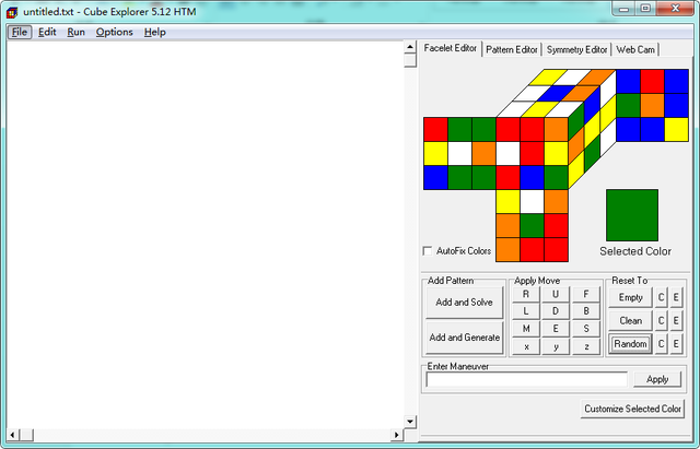
Startup window of software is as follows
You can manually edit the cube on the right side of the Facelet Editor tab.
Left-click the center of the cube can extract color , right-click other locations can be filled with the currently selected color. Repeat the above steps until you've filled out the colors of a Cube . As shown below:
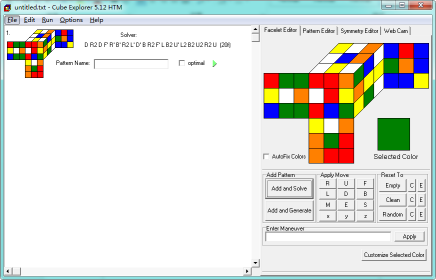
Click the "Add and Solve", the program will generate the solution of the cube on the left side:
Click ![]() on the left side , the program will try to find solutions that will has fewer number of steps , but time-consuming of this process can take up to half an hour. Of course, maybe it could not find the solution of less steps. After got the solution , take the formula to operate and then solve the cube .
on the left side , the program will try to find solutions that will has fewer number of steps , but time-consuming of this process can take up to half an hour. Of course, maybe it could not find the solution of less steps. After got the solution , take the formula to operate and then solve the cube .
More details of Cube Explorer, please refer to the attachment.
Instructions For The Use Of Arduino
Open MyCube.ino file which is already debugged , click the "Upload" button to compile and upload the code to the Arduino Uno. After the completion, the Arduino is ready to restore the cube .
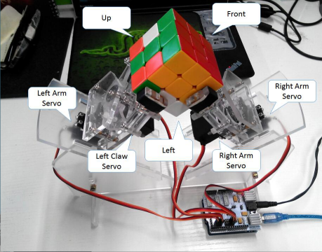
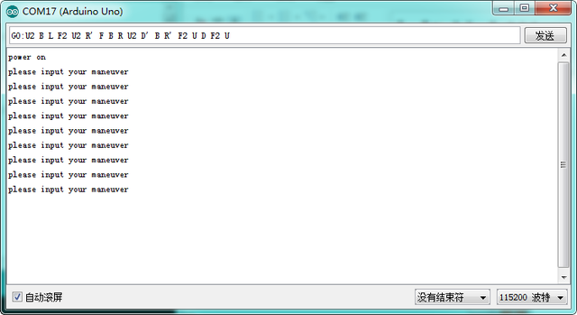
Use Cube Explorer to get the solution of a cube , the form of cube solution is as follows : U2 BL F2 u2 R 'FBR U2 D' B R 'F2 UD F2 U (18f), different cube have different solutions, take the above solution as an example, Add "GO:" these three characters on the top, do not have spaces after the colon, delete the last parenthesis and the contents of parenthesis, the resulting formula is as follows : "GO: U2 BL F2 U2 R 'FBR U2 D 'B R' F2 UD F2 U ". Connect the Arduino to the computer , power the Power Base Shield, When Arduino is powered up, it will adjust each arm to the initial position , then you can place the cube . The method of placing the cube as the blow picture :
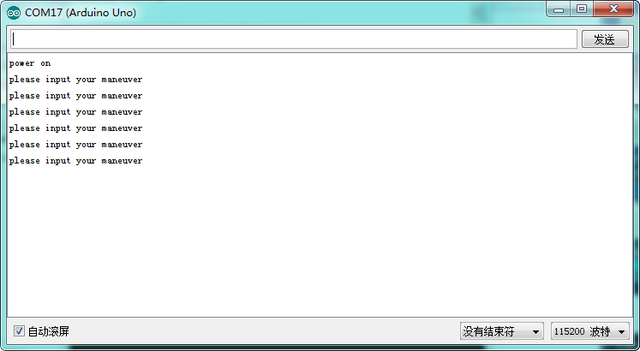
Open the Arduino IDE 's serial monitor , Arduino will continue to send "please input your maneuver"without entering a formula.
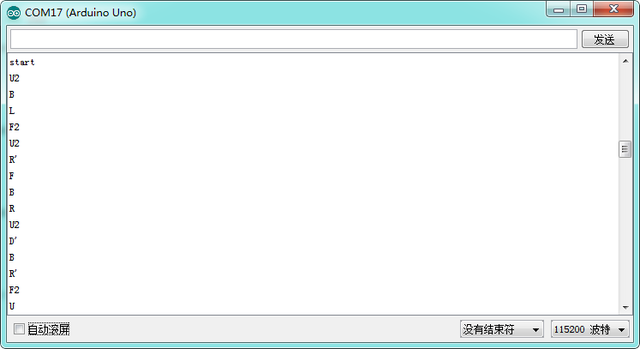
Enter the formula which is obtained from above and transmitted, the robot will automatically perform the operation according to the equation and restore the cube . As shown below:
Robot performing each step, the steps currently being executed will be displayed on the serial port, and "error or end" will be displayed in serial after the restoration is complete.
"finish" will be display on the terminal after complete , the next time when you need to restore, please press "RESET" button on Arduino board.
If the cube drop, arm stuck etc during the the restore process, you can press the "RESET" key to return to the initial position of the robot arm.
Code Explanation
In the program, left arm located D5 port, left paw located D9 port, right arm located D10 port, right paw located D11 port. Users can modify these settings according to their own situation . Its code is as follows :
//The pins of the steering engine can be set to the following positions 3,5,6,9,10,11
#define LEFT_ARM   5
#define LEFT_CLAW  9
#define RIGHT_ARM  10
#define RIGHT_CLAW 11
Code which lines 23 is the time interval between each movement , in milliseconds , it can be modified according to the actual situation. After test, If the delay is too small, it will lead to start the next action but the last action has not been finished yet. We recommend that delay should be more than 400 milliseconds. Code is as follows :
//the delay betweem each movement(We recommend that delay should be more than 400 milliseconds)
#define DELAY 500
According to decomposition movements of restore the cube, we can get the following 8 basic movements : Left arm clockwise rotate Rubik cube, Left arm anticlockwise rotate Rubik cube, Left arm clockwise rotate the side of the Magic cube, Left arm anticlockwise rotate the side of the Magic cube,right arm clockwise rotate Rubik cube, right arm anticlockwise rotate Rubik cube, right arm clockwise rotate the side of the Magic cube, right arm anticlockwise rotate the side of the Magic cube.
A basic operation is achieved by operating the left and right arm, the left and right paw. For example, the code of left arm clockwise rotate Rubik cube is as follows :
void LeftCWBody()
{
 RightClaw.write(RIGHT_CLAW_OPEN);
 delay(DELAY);
 LeftArm.writeMicroseconds(LEFT_ARM_180);
 delay(DELAY);
 RightClaw.write(RIGHT_CLAW_CLOSE);
 delay(DELAY);
 LeftClaw.write(LEFT_CLAW_OPEN);
 delay(DELAY);
 LeftArm.writeMicroseconds(LEFT_ARM_90);
 delay(DELAY);
 LeftClaw.write(LEFT_CLAW_CLOSE);
 delay(DELAY);
 }
The first step in this action is open the right claw: RightClaw.write(RIGHT_CLAW_OPEN);and RIGHT_CLAW_OPEN is the open angle of right claw in program macros defined.
The second action is left arm clockwise rotation of 90 degrees: leftArm.writeMicroseconds(LEFT_ARM_180); and LEFT_ARM_180 is the value of left arm location at 180 degree in program macros defined.
Using the write method of Servo can directly control the angle of the steering , due to the required accuracy of left and right claw to reduce the cube is low, therefore use the method of write ( )to control directly. Right and left arms can accurately stop at the specified angle directly affect whether the cube can be successfully restored , so we use writeMicroseconds () to control the angle of the left and right arm. We know that servos using PWM 20ms to control the angle , we can control the PWM duty cycle to precisely control the angle of the steering gear , we can calculate the time of the duty cycle by following formula,
High-level duration = angle * ( 100/ 9 ) + 500
The unit of high-level duration is microsecond.
Because the performance of each servo is slightly different, so we need to adjust the duration of the high level to let the steering gear accurately stopped at an angle we need.
The 8 basic operation mentioned above correspond to the following functions:
void LeftCWBody();      //Left arm clockwise rotate Rubik cube
void LeftAWBody();      //Left arm anticlockwise rotate Rubik cube
void LeftCWSide();      //Left arm clockwise rotate the side of the Magic cube
void LeftAWSide();      //Left arm anticlockwise rotate the side of the Magic cube
void RightCWBody();     //right arm clockwise rotate Rubik cube
void RightAWBody();     //right arm anticlockwise rotate Rubik cube
void RightCWSide();     //right arm clockwise rotate the side of the Magic cube
void RightAWSide();     //right arm anticlockwise rotate the side of the Magic cube
Make different combinations of the above 8 basic operations,you can get some actions to restore the cube. The combination of these three actions(right arm clockwise rotate Rubik cube,Left arm clockwise rotate the side of the Magic cube,right arm anticlockwise rotate Rubik cube),you can get the operation of right side rotate 90 degrees clockwise
  void ActR()
  {
  RightCWBody();
  LeftCWSide();
  RightAWBody()
  }
The 18 basic operations of restoring the cube: right side rotate 180 degrees,right side rotate 90 degrees clockwise,right side rotate 90 degrees anticlockwise,left side rotate 180 degrees,left side rotate 90 degrees clockwise,left side rotate 90 degrees anticlockwise,upper side rotate 180 degrees,upper side rotate 90 degrees clockwise,upper side rotate 90 degrees anticlockwise, under side rotate 180 degrees, under side rotate 90 degrees clockwise,under side rotate 90 degrees anticlockwise,front side rotate 180 degrees,front side rotate 90 degrees clockwise,front side rotate 90 degrees anticlockwise,behind side rotate 180 degrees,behind side rotate 90 degrees clockwise,behind side rotate 90 degrees anticlockwise.
void ActR2();           //right side rotate 180 degrees
void ActRp();           //right side rotate 90 degrees clockwise
void ActR();            //right side rotate 90 degrees anticlockwise
void ActL2();           //left side rotate 180 degrees
void ActLp();           //left side rotate 90 degrees clockwise
void ActL();            //left side rotate 90 degrees anticlockwise
void ActU2();           //upper side rotate 180 degrees
void ActUp();           //upper side rotate 90 degrees clockwise
void ActU();            //upper side rotate 90 degrees anticlockwise
void ActD2();           //under side rotate 180 degrees
void ActDp();           // under side rotate 90 degrees clockwise
void ActD();            //under side rotate 90 degrees anticlockwise
void ActF2();           //front side rotate 180 degrees
void ActFp();           //front side rotate 90 degrees clockwise
void ActF();            //front side rotate 90 degrees anticlockwise
void ActB2();           //behind side rotate 180 degrees
void ActBp();           //behind side rotate 90 degrees clockwise
void ActB();            //behind side rotate 90 degrees anticlockwise
The 18 movements which correspond to an item of the cube formula.In accordance with formula of the Rubik's cube to execute in order that can restore a Rubik's cube.
