Difference between revisions of "16 X 2 LCD Keypad Shield for Arduino"
Katherine.d (talk | contribs) (→Introduction) |
(→Support) |
||
| Line 58: | Line 58: | ||
== Support == | == Support == | ||
| + | |||
| + | If you have questions or other better design ideas, you can go to our [http://www.linksprite.com/forum/index.php forum] to discuss or creat a ticket for your issue at [http://www.linksprite.com/support/ linksprite support]. | ||
== Resources == | == Resources == | ||
Revision as of 06:30, 12 November 2012
Contents
Introduction
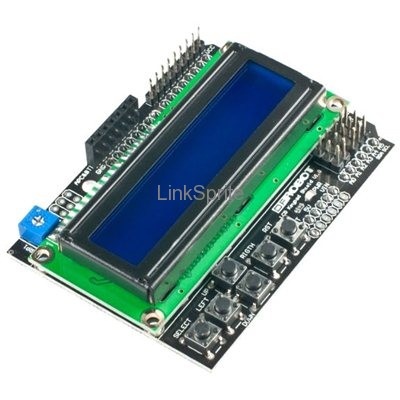
LCD keypad shield for Arduino operates at 5V
- Includes a 2x16 LCD display and 6 momentary push buttons
- Use digital pins 4, 5, 6, 7, 8, 9, 10, and analog pin 0 to interface with the LCD
- Do not use Pin 10 while this shield is connected
- LCD color may vary (green or blue)
The DFRobot LCD Keypad Shield for Arduino includes a 2x16 LCD display and 6 momentary push buttons. Pins 4, 5, 6, 7, 8, 9 and 10 are used to interface with the LCD. Analog Pin 0 is used to read the pushbuttons. The shield operates at 5V.
Note: all new LCD shields with paper enclosure use pin 10 as brightness control.
Model:LCD_16_2_SHIELD
Features
- Has a contrast adjustment
- 1 Simulation I simulation five keystrokes
- Laminated design and easy to expand
Application Ideas
Cautions
The warnings and wrong operations possible cause dangerous.
Schematic
Specification
Pin definition and Rating
Mechanic Dimensions
Usage
Hardware Installation
Programming
FAQ
Please list your question here:
Support
If you have questions or other better design ideas, you can go to our forum to discuss or creat a ticket for your issue at linksprite support.
Resources
- LED Strip driver eagle files
- Schematic in PDF
- LEDStripDriver library
- Chip datasheet(optional)
How to buy
See Also
Other related products and resources.
Licensing
This documentation is licensed under the Creative Commons Attribution-ShareAlike License 3.0 Source code and libraries are licensed under GPL/LGPL, see source code files for details.
