Difference between revisions of "Quad-band GPRS/GSM Shield for Arduino"
(→Tutorial II) |
(→Usage) |
||
| Line 49: | Line 49: | ||
== Usage == | == Usage == | ||
| + | This tutorial covers the GPRS/GSM SM5100B Shield: | ||
| + | http://www.cutedigi.com/arduino-shields/quad-band-gprsgsm-shield-for-arduino-cellular-module-included.html | ||
| − | + | The shield must be powered by a wall adapter with ''12V, 1A''. | |
| − | |||
=== Hardware Installation === | === Hardware Installation === | ||
Revision as of 08:31, 31 December 2012
Contents
Introduction
Model:Arduino_SM5100_1
Features
Application Ideas
Cautions
Schematic
Specification
Pin definition and Rating
Mechanic Dimensions
Usage
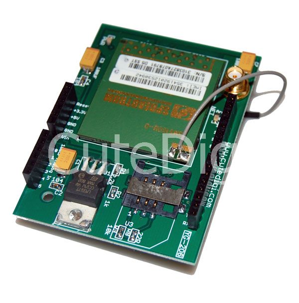
This tutorial covers the GPRS/GSM SM5100B Shield: http://www.cutedigi.com/arduino-shields/quad-band-gprsgsm-shield-for-arduino-cellular-module-included.html
The shield must be powered by a wall adapter with 12V, 1A.
Hardware Installation
- J1 and J2 are used to choose how RX/TX of SM5100B is going to connected to Arduino.
- RX/TX is the RX/TX of SM5100B module.
- MTX/MRX is the TX/RX of Atmega328.
- D3 and D2 are the I/O of Atmega328 if soft serial is used.
Programming
Tutorial II
Now we are going to use atmega328P's UART to talk to USB, and soft serial of atmega328P to talk to Sm5100B.
Before we do that, we have to change SMB5100's data rate to 9600 as soft serial can't go to 119200. In first tutorial setup, do: AT+IPR=9600 to set the baud rate to 9600.
Now set the jumper RX to D3, and TX to D2. SO that atmega328P's UART to talk to USB and soft serial of atmega328P to talk to SM5100B:
<syntaxhighlight lang="c">
/* SparkFun Cellular Shield - Pass-Through Sample Sketch SparkFun Electronics Written by Ryan Owens CC by v3.0 3/8/10 Thanks to Ryan Owens and Sparkfun for sketch */
- include <NewSoftSerial.h> //Include the NewSoftSerial library to send serial commands to the cellular module.
- include <string.h> //Used for string manipulations
char incoming_char=0; //Will hold the incoming character from the Serial Port. NewSoftSerial cell(2,3); //Create a 'fake' serial port. Pin 2 is the Rx pin, pin 3 is the Tx pin. void setup() {
//Initialize serial ports for communication.
Serial.begin(9600); cell.begin(9600); Serial.println("Starting SM5100B Communication..."); } void loop() { //If a character comes in from the cellular module... if(cell.available() >0) { incoming_char=cell.read(); //Get the character from the cellular serial port. Serial.print(incoming_char); //Print the incoming character to the terminal. } //If a character is coming from the terminal to the Arduino... if(Serial.available() >0) { incoming_char=Serial.read(); //Get the character coming from the terminal cell.print(incoming_char); //Send the character to the cellular module. } }
</syntaxhighlight>
FAQ
Please list your question here:
Support
If you have questions or other better design ideas, you can go to our forum to discuss or creat a ticket for your issue at linksprite support.
Resources
How to buy
See Also
Other related products and resources.
Licensing
This documentation is licensed under the Creative Commons Attribution-ShareAlike License 3.0 Source code and libraries are licensed under GPL/LGPL, see source code files for details.
