Difference between revisions of "TTL Level Shifter"
Katherine.d (talk | contribs) (→Description) |
Katherine.d (talk | contribs) (→Description) |
||
| Line 9: | Line 9: | ||
[[File:TTL_Level_shifter.jpg | 400px]] | [[File:TTL_Level_shifter.jpg | 400px]] | ||
| + | |||
| + | == Schematic == | ||
| + | [https://s3.amazonaws.com/linksprite/breakout/TTL_level_shifter/level_shifter.pdf schematic of TTL level shifter in PDF] | ||
| + | |||
| + | == Resource == | ||
| + | [https://s3.amazonaws.com/linksprite/breakout/TTL_level_shifter/BSS138.pdf BSS138] | ||
Latest revision as of 04:33, 21 February 2013
Description
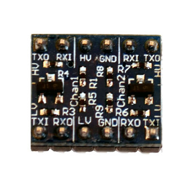
If you've ever tried to connect a 3.3V device to a 5V system, you know what a challenge it can be. The LinkSprite logic level shifter is a small device that safely steps down 5V signals to 3.3V and steps up 3.3V to 5V. This level converter also works with 2.8V and 1.8V devices. Each level converter has the capability of converting 4 pins on the high side to 4 pins on the low side. Two inputs and two outputs are provided for each side.
Bread board friendly! Can be used with normal serial, I2C, SPI, and any other digital signal. Does not work with an analog signal.
The level converter is very easy to use. The board needs to be powered from the two voltages sources (high voltage and low voltage) that your system is using. High voltage (5V for example) to the 'HV' pin, low voltage (2.8V for example) to 'LV', and ground from the system to the 'GND' pin.
Pins are labeled as Inputs and Outputs. These are relative to the board. A digital one going into the RXI pin on the 5V side will show up on the RXO pin on the 3.3V side as 3.3V. A digital one going into the TXI pin on the 3.3V side will show up on the TXO pin on the 5V side as 5V.
Schematic
schematic of TTL level shifter in PDF
