Difference between revisions of "LinkerKit for Raspberry Pi"
(→Linker LED) |
(→Linker LED) |
||
| Line 100: | Line 100: | ||
===Linker Light Sensor=== | ===Linker Light Sensor=== | ||
| − | To use this module with RPI, we need a | + | To use this module with RPI, we need a [http://linksprite.com/wiki/index.php5?title=Linker_kit_Base_Shield_for_Raspberry_Pi_with_ADC_Interface shield ]. |
If you don't have this shield, you can follow the instructions at [http://scruss.com/blog/2013/02/02/simple-adc-with-the-raspberry-pi/ here]. | If you don't have this shield, you can follow the instructions at [http://scruss.com/blog/2013/02/02/simple-adc-with-the-raspberry-pi/ here]. | ||
Revision as of 15:47, 31 July 2013
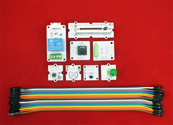
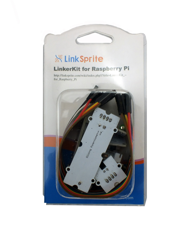
This pack includes the following components:
- Button Module [LINKER_BUTTON][118101002]
- 5mm Green LED Module [LINKER_5MMGREEN][118101001]
- LDR Module [LINKER_LDR][118101003]
- Thermal Module [LINKER_TEMP][118101005]
- Linear/Slide Potentiometer Module [LINKER_LINEPOTENT][118101006]
- Tilt Module [LINKER_TLT][118101004]
- Touch Sensor Module [LINKER_TOUSEN][118101007]
- Relay Module [LINKER_RELAY][118101008]
- Female to female jumper wires
Tutorial
In this tutorial, we are going to explain how to use Python to do the experiments:
Environment Setup
Now we will install python-pip (pip is a package used to install and manage python software package, and it is used replace esay_install):
sudo apt-get install python-imaging python-imaging-tk python-pip python-dev git
Next, we will install spidev using pip:
sudo pip install spidev
Then we will install WiringPi (the driver for IOs on Raspberry pi, that can be used in C, shell script or Python, etc):
sudo pip install wiringpi
Linker Button
Connect linker_led to pin 27 of RPI, connect linker_button to pin 23 of RPI
Python code:
<syntaxhighlight lang="c">
import RPi.GPIO as GPIO
led_pin = 27 button_pin = 23
GPIO.setmode( GPIO.BCM ) GPIO.setup( led_pin,GPIO.OUT ) GPIO.setup( button_pin, GPIO.IN, pull_up_down=GPIO.PUD_UP)
print ("\nlinker_led pin 27 , linker_button pin 23\n")
while True: if GPIO.input(button_pin): GPIO.output(led_pin,True) else : GPIO.output(led_pin,False) </syntaxhighlight>
Linker LED
Connect linker led to pin 27 of RPI.
Python code:
<syntaxhighlight lang="c">
import RPi.GPIO as GPIO import time
led_pin = 27
GPIO.setmode(GPIO.BCM) GPIO.setup(led_pin,GPIO.OUT)
print "\nlinker led pin 27\n"
while True:
GPIO.output(led_pin,True) time.sleep(0.5) GPIO.output(led_pin,False) time.sleep(0.5) </syntaxhighlight lang="c">
Linker Light Sensor
To use this module with RPI, we need a shield .
If you don't have this shield, you can follow the instructions at here.

