Difference between revisions of "Relay Module"
Qian.zhang (talk | contribs) |
|||
| Line 1: | Line 1: | ||
| + | ==Introduction== | ||
| + | The Linker Relay Module is a digital normally-open switch. Through it, you can control circuit of high voltage with low voltage, say 5V on the controller. There is an indicator LED on the board, which will light up when the controlled terminals get closed. | ||
| + | |||
[[File:Linker relay.jpg]] | [[File:Linker relay.jpg]] | ||
| − | == | + | == Schematics == |
| + | *[https://s3.amazonaws.com/linksprite/LinkerKit/link_relay.pdf Schematics] | ||
| + | ==Application Ideas== | ||
| + | '''test''' | ||
<syntaxhighlight lang="c"> | <syntaxhighlight lang="c"> | ||
/* | /* | ||
| − | + | Linker Relay | |
the Relay will turn on for 5s and then turn off for 5s, and so on. | the Relay will turn on for 5s and then turn off for 5s, and so on. | ||
| Line 37: | Line 43: | ||
Hot line of incoming port is connected to COM. | Hot line of incoming port is connected to COM. | ||
Hot line of the outgoing port is connected to NC. | Hot line of the outgoing port is connected to NC. | ||
| − | |||
| − | |||
| − | |||
==How to buy== | ==How to buy== | ||
Here to buy Relay Module on [http://store.linksprite.com/relay-module-of-linker-kit-for-pcduino-arduino/ store] | Here to buy Relay Module on [http://store.linksprite.com/relay-module-of-linker-kit-for-pcduino-arduino/ store] | ||
Revision as of 05:37, 11 April 2014
Introduction
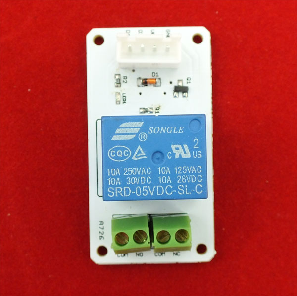
The Linker Relay Module is a digital normally-open switch. Through it, you can control circuit of high voltage with low voltage, say 5V on the controller. There is an indicator LED on the board, which will light up when the controlled terminals get closed.
Schematics
Application Ideas
test <syntaxhighlight lang="c">
/*
 Linker Relay
 the Relay will turn on for 5s and then turn off for 5s, and so on.

 This example code is in the public domain.
*/
int RelayControlPin = 13; void setup() {
 // initialize the digital pin as an output.
 // Pin 13 has an LED connected on most Arduino boards:
 pinMode(RelayControlPin, OUTPUT);
}
void loop() {
 digitalWrite(RelayControlPin, HIGH);   // set the LED on
 delay(500);              // wait for a second
 digitalWrite(RelayControlPin, LOW);    // set the LED off
 delay(500);              // wait for a second
}
</syntaxhighlight>
Wiring instructions:
Suppose that the incoming port is the one that supply power, and the outgoing is connected to the device to be controlled.
Neural line of the incoming port are connected to the that of the outgoing port. Hot line of incoming port is connected to COM. Hot line of the outgoing port is connected to NC.
How to buy
Here to buy Relay Module on store
