Difference between revisions of "Redback WiFi Platform Compatible With Arduino Nano"
Katherine.d (talk | contribs) (→Introduction) |
Qian.zhang (talk | contribs) (→Resources) |
||
| (One intermediate revision by one other user not shown) | |||
| Line 87: | Line 87: | ||
*[https://github.com/linksprite/ZG2100BasedWiFiShield Github] | *[https://github.com/linksprite/ZG2100BasedWiFiShield Github] | ||
*[http://player.youku.com/player.php/sid/XMzkyMDg0NDQ0/v.swf Tutorial Video] | *[http://player.youku.com/player.php/sid/XMzkyMDg0NDQ0/v.swf Tutorial Video] | ||
| + | *[http://learn.linksprite.com/arduino/shields/how-to-use-redback/ Tutorial 1] | ||
| + | *[http://learn.linksprite.com/arduino/shields/redback-and-linker-temperature-experiment/ Tutorial 2] | ||
== How to buy == | == How to buy == | ||
| − | + | Here to buy Redback on [http://store.linksprite.com/wifi-redback-1-0-arduino-yellowjacket-compatible/ store] | |
| − | |||
| − | |||
| − | |||
== See Also == | == See Also == | ||
Latest revision as of 01:59, 20 May 2014
Contents
Introduction
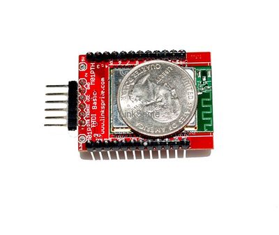
Have a project that is space constrained? Want to also get wireless connectivity out of it? Introducing the YellowJacket, an Arduino compatible device based on the Arduino mini. This is as small as it can get with the wireless module. The YellowJacket is a two side surface mount device, so you'll need to plan accordingly for components on both sides of the board in your wireless project.
Similar to the Arduino mini and to conserve space, the YellowJacket will require a USB breakout board to be able to program it. We will be providing the YellowJacket in two variants. One will have a 90° male header attached along one of the shorter edges to allow for easy connection to the USB breakout board. The other will have no header, and will require you to come up with your own mechanism for programming the device (i.e. spring clips).
Features
- smallest size possible with wireless capability
- up to 12 digital I/O pins[1]
- 6 analog input pins
- Atmel Mega 328P microprocessor
- 32KB flash RAM (2KB used for bootloader)
- 2KB SRAM
- 1KB EEPR
- 802.11b 1 and 2 mbps wireless connectivity
- on-board PCB antenna
- supports infrastructure mode (BSS) and adhoc (IBSS) network modes
- support for WEP, WPA, and WPA2 security
- LED attached to digital pin 9 used to indicate a successful wireless connection
Application Ideas
Cautions
Schematic
Specification
Pin definition and Rating
For WiFi usage, a minimum of 5 digital pins are required: 4 for SPI and 1 for interrupt. The SPI bus can be shared with other SPI devices, but the CS pin cannot be modified from pin 10. Your other SPI device must have a switchable SPI CS pin, or a hardware modification needs to be performed.
Mechanic Dimensions
Usage
Hardware Installation
Programming
FAQ
Please list your question here:
Support
If you have questions or other better design ideas, you can go to our forum to discuss or creat a ticket for your issue at linksprite support.
Resources
How to buy
Here to buy Redback on store
See Also
Other related products and resources.
Licensing
This documentation is licensed under the Creative Commons Attribution-ShareAlike License 3.0 Source code and libraries are licensed under GPL/LGPL, see source code files for details.

