Difference between revisions of "CuHead WiFi Shield for Arduino V2.0"
Katherine.d (talk | contribs) (→Specification) |
Yajuan.dai (talk | contribs) (→Introduction) |
||
| (29 intermediate revisions by 3 users not shown) | |||
| Line 1: | Line 1: | ||
== Introduction == | == Introduction == | ||
| − | + | CuHead WiFi shield Version 2.0! It has the EEPROM that can be used to store the webpages, it also has the batterty charging components populated. | |
| − | + | This is the shield you need to get Wi-Fi connectivity to your Arduino-based project! This shield provides 802.11b connectivity and is a direct drop-on plug-and-play solution to your Arduino Diecimila/Duemilanove. | |
| − | + | The second revision of this board has all the components in surface mount form. The new and exciting feature of the second revision of this board is the addition of a 16Mbit serial flash for storing web pages and other data! This additional storage space can be used for storing more complex and feature rich webpages, as well as sensor type data to be downloaded at a future time. | |
| − | + | [[File:CuHead WiFi Shield for Arduino V2.0A.jpg]] | |
| − | + | == Features == | |
| + | |||
| + | *Add-on shield built for Arduino Diecimila, Duemilanove and Uno R2/R3 | ||
| + | **Dimensions, shape, even color match exactly! | ||
| + | **True plug-n-play solution | ||
| + | *Uses SPI for host communication (max speed 25MHz) | ||
| + | *All Arduino headers brought out for easy access | ||
| + | *Easy access reset button on-board | ||
| + | *On-board PCB antenna | ||
| + | *Switchable interrupt pin usage between INT0 and digital pin 8 | ||
| + | *Switchable LED on digital pin 9 | ||
| + | *Switchable CS pin for serial flash between digital pin 10 and digital pin 7 | ||
| − | |||
'''Standard spec''' | '''Standard spec''' | ||
| Line 81: | Line 91: | ||
== Application Ideas == | == Application Ideas == | ||
| − | '''Video | + | '''Video Introduction''' |
*[http://v.youku.com/v_show/id_XMzkxMjI2NDgw.html Features of CuHead V2.0] | *[http://v.youku.com/v_show/id_XMzkxMjI2NDgw.html Features of CuHead V2.0] | ||
| Line 122: | Line 132: | ||
=== Hardware Installation === | === Hardware Installation === | ||
| − | ''' | + | '''Prepare Hardware''' |
*Cuhead WiFi Shield V2.0 module | *Cuhead WiFi Shield V2.0 module | ||
| Line 135: | Line 145: | ||
[[File:Cuhead 3.jpg]] | [[File:Cuhead 3.jpg]] | ||
| − | ''' | + | '''Prepare Software''' |
*Arduino 1.0 | *Arduino 1.0 | ||
| Line 192: | Line 202: | ||
== FAQ == | == FAQ == | ||
| − | '''Q1. Program can't be compiled''' | + | *'''Q1. Program can't be compiled''' |
| − | + | **Check these if you found that the example we provide cannot compile. Whether you choose the right Board. You should choose the board you are using when compile. Here enter ZG2100BasedWiFiShield[[File:Cuhead 12.jpg]] , and open apps-conf.h | |
| − | |||
| − | |||
| − | Whether you choose the right Board. You should choose the board you are using when compile. | ||
| − | |||
| − | Here enter ZG2100BasedWiFiShield[[File:Cuhead 12.jpg]] , and open apps-conf.h | ||
[[File:Cuhead 13.jpg]] | [[File:Cuhead 13.jpg]] | ||
| − | |||
| − | |||
| − | You have to change it here according to your needs. To different examples, the macro definition is different, the default is: | + | To prevent repeated quotation of the same file, which will cause compile error like duplicate definition and nested quoted. You have to change it here according to your needs. To different examples, the macro definition is different, the default is: |
'''#define APP_WISERVER''' | '''#define APP_WISERVER''' | ||
[[File:Cuhead 14.jpg]] | [[File:Cuhead 14.jpg]] | ||
| − | + | ||
| + | |||
If you want to use another example, such as how to use webserver.h, | If you want to use another example, such as how to use webserver.h, | ||
'''#define APP_WEBSERVER''' | '''#define APP_WEBSERVER''' | ||
| − | |||
'''//#define APP_WISERVER''' | '''//#define APP_WISERVER''' | ||
| − | + | *Q2. Red LED(D1)not on''' | |
| − | + | **If the program has been downloaded to Arduino, yet red LED(D1)on Cuhead V1.0 is not on, which means Wi-Fi not connected,please check below part. Check the IP address,default gate way and subnet mask in the code if it is right with the WiFi routor settings. And check the SSID,PASSWORD and encryption method. Or you can reset Cuhead V2.0/Arduino module and reconnect them. | |
| − | |||
| − | |||
| − | Check the IP address,default gate way and subnet mask in the code if it is right with the WiFi routor settings. | ||
| − | |||
| − | And check the | ||
| − | |||
Check the jump line parts: | Check the jump line parts: | ||
| − | + | ***INTX1, used to choose to interrupt mode, jump line 1, 2 pin is D8, jump line 2, 3 pin is D2. No influence on the use of Cuhead V2.0, not normally use. | |
| − | *INTX1, used to choose to interrupt mode, jump line 1, 2 pin is D8, jump line 2, 3 pin is D2. No influence on the use of Cuhead V2.0, not normally use. | + | ***Flash_sn, jump line 1, 2 pin is SS, jump line 2, 3 pin is CS, when you using Wi-Fi choice SS, make Flash invalid. |
| − | + | ***Wi-Fi connection indicator light, jump line 1, 2 pin. Cuhead V2.0 leave factory, need to jump line of the part we have adjusted, you can use directly. | |
| − | *Flash_sn, jump line 1, 2 pin is SS, jump line 2, 3 pin is CS, when you using Wi-Fi choice SS, make Flash invalid. | ||
| − | |||
| − | *Wi-Fi connection indicator light, jump line 1, 2 pin. Cuhead V2.0 leave factory, need to jump line of the part we have adjusted, you can use directly. | ||
'''Q3. Using UNO R3''' | '''Q3. Using UNO R3''' | ||
A3:When Cuhead V2.0 connected to Arduino UNO R3, Cuhead V2.0 may be unable to connect to wifi. | A3:When Cuhead V2.0 connected to Arduino UNO R3, Cuhead V2.0 may be unable to connect to wifi. | ||
| + | |||
| + | Note: This issue is only for Arduino R3 of early days. Current version doesn't have this issue anymore. | ||
You need to download the latest version of the Bootloader to Arduino microcontroller (ATmegaXXXX). | You need to download the latest version of the Bootloader to Arduino microcontroller (ATmegaXXXX). | ||
| Line 251: | Line 247: | ||
And you may have to pull pins to match the correct SPI pins to get it working. | And you may have to pull pins to match the correct SPI pins to get it working. | ||
| + | |||
| + | '''Q5.Does it work with Arduino Uno3 as advertised? Does it use the Arduino WiFi libraries?''' | ||
| + | |||
| + | It does work with Uno R3. It was having problem with old Uno R2 that has older bootloader. | ||
| + | |||
| + | Q: Thanks for your quick response. The board seems to work great w/ the Uno3. | ||
| + | |||
| + | Most of the examples compile and work; except for the UDP_APP. I'm using the Arduino 1.03 compiler, and I have changed the #define in the app_conf.h file. | ||
| + | |||
| + | I'll keep working through it, but would be like to know if this works for you. | ||
| + | |||
| + | A: For UDP, example, we also need to modify uip-conf.h under libraries\linksprite\WiFiShield. | ||
| + | |||
| + | We need to locate | ||
| + | |||
| + | #define UIP_CONF_UDP 0 | ||
| + | |||
| + | change it to: | ||
| + | |||
| + | #define UIP_CONF_UDP 1 | ||
| + | |||
| + | |||
| + | '''Q6. [[Can CuHead WiFi Shield be used with Arduino Mega?]]''' | ||
| + | |||
| + | To make the WiShield work on mega follow the NKC tutorial on wiring up the Ethernet shield http://mcukits.com/2009/04/06/arduino-ethernet-shield-mega-hack/ | ||
| + | |||
| + | and make the following changes to spi.h (in hardware\libraries\wishield): | ||
| + | |||
| + | |||
| + | #define SPI0_SS_BIT BIT0 | ||
| + | ... | ||
| + | #define SPI0_SCLK_BIT BIT1 | ||
| + | ... | ||
| + | #define SPI0_MOSI_BIT BIT2 | ||
| + | ... | ||
| + | #define SPI0_MISO_BIT BIT3 | ||
| + | ... | ||
| + | #define SPI0_Init() PRR0 = 0x00;\ | ||
| + | DDRB |= SPI0_SS_BIT|SPI0_SCLK_BIT|SPI0_MOSI_BIT|LEDConn_BIT;\ | ||
| + | DDRB &= ~SPI0_MISO_BIT;\ | ||
| + | PORTB = SPI0_SS_BIT;\ | ||
| + | SPCR = 0x50;\ | ||
| + | SPSR = 0x01 | ||
| + | ... | ||
| + | #define ZG2100_CS_BIT BIT0 | ||
| + | ... | ||
| + | #define LEDConn_BIT BIT5 | ||
| + | |||
| + | |||
| + | the Mega not only remapped the SPI pins, it also remapped the interrupt pins. The ZeroG board triggers an interrupt when it needs the host to do something. This is why the WiShield would init, and then nothing else. If you attach a scope or a LED to the WiShield interrupt pin (pin2/int0), you can see it going low but never getting serviced. | ||
| + | |||
| + | |||
| + | On the Duemilanove, Arduino Pin 2 goes to INT0/PD2 on the ATMega328. On the Mega, Arduino Pin 2 goes to PE4, which is not an interrupt at all. | ||
| + | |||
| + | |||
| + | (1) Bend out pin 2 on the WiShield similar to how pins 10,11,12,13 are bent out. | ||
| + | |||
| + | (2) Jumper this pin on the WiShield to pin 21 on the Arduino Mega. | ||
| + | |||
| + | (3) In "WiServer.cpp" and "WiShield.cpp" change "attachInterrupt(0, zg_isr, LOW);" to "attachInterrupt(2, zg_isr, LOW);". This may be counterintutive, but from the documentation, it seems the Arduino development environment maps interrupt pin 2 to 21. See [http://www.arduino.cc/en/Reference/AttachInterrupt AttachInterrupt] for details. | ||
| + | |||
| + | |||
| + | For extra credit, if you don't like mangling the pins on your beautiful WiShield, connect the jumpers and turn pins 2,10,11,12,13 into high-impedance inputs. Note this means you can't use them for other purposes but they can remain electrically connected. | ||
| + | |||
| + | |||
| + | |||
| + | pinMode(2, INPUT); | ||
| + | |||
| + | pinMode(10, INPUT); | ||
| + | |||
| + | pinMode(11, INPUT); | ||
| + | |||
| + | pinMode(12, INPUT); | ||
| + | |||
| + | pinMode(13, INPUT); | ||
| + | |||
| + | |||
| + | |||
| + | '''Q7. With this shield can I connect the arduino to my internet router and send instructions from my phone, when I’m at work for example, and say to my arduino to open my air-condition at home? ''' | ||
| + | ** Yes. It can. | ||
== Support == | == Support == | ||
| Line 259: | Line 335: | ||
*[http://www.linksprite.com/article/shownews.php?lang=en&id=58 source code github] | *[http://www.linksprite.com/article/shownews.php?lang=en&id=58 source code github] | ||
| − | |||
*[http://www.linksprite.com/article/shownews.php?lang=en&id=106 Can CuHead WiFi Shield be used with Arduino Mega?] | *[http://www.linksprite.com/article/shownews.php?lang=en&id=106 Can CuHead WiFi Shield be used with Arduino Mega?] | ||
| + | *[https://s3.amazonaws.com/linksprite/Shields/CuHead_Arduino/Wifi+Shield+Chip-MRF24WB0MADatasheet.pdf Wifi Shield Chip-MRF24WB0MA Datasheet] | ||
| + | *[https://s3.amazonaws.com/linksprite/Shields/CuHead_Arduino/Cuhead+Wifi+Shield+for+Arduino+User+Guide_v1.pdf User Guide of CuHead] | ||
| + | *[https://github.com/linksprite/ZG2100BasedWiFiShield ZG2100 based Wifi Shield] | ||
| + | *[http://www.alldatasheet.com/view.jsp?Searchword=ZG2100MC datasheet of ZG2100MC] | ||
| − | *[http://www. | + | === Blogs === |
| + | *[http://www.cutedigi.com/blog/?p=19 Detailed tutorial on CuHead by CuteDigi] | ||
| + | *[http://www.cutedigi.com/blog/?p=107 How to Compile and Test Sample SocketApp of LinkSprite’s CuHead WiFi Shield] | ||
| + | *[http://www.cutedigi.com/blog/?p=101 How to Compile Sample UDPApp of LinkSprite’s CuHead WiFi Shield] | ||
== How to buy == | == How to buy == | ||
| − | Here to buy CuHead V2.0 [http:// | + | Here to buy CuHead V2.0 on [http://store.linksprite.com/cuhead-wifi-shield-v2-0-for-arduino/ store] |
== See Also == | == See Also == | ||
Latest revision as of 09:10, 27 August 2014
Contents
Introduction
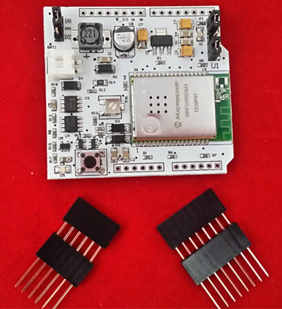
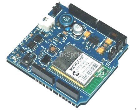
CuHead WiFi shield Version 2.0! It has the EEPROM that can be used to store the webpages, it also has the batterty charging components populated.
This is the shield you need to get Wi-Fi connectivity to your Arduino-based project! This shield provides 802.11b connectivity and is a direct drop-on plug-and-play solution to your Arduino Diecimila/Duemilanove.
The second revision of this board has all the components in surface mount form. The new and exciting feature of the second revision of this board is the addition of a 16Mbit serial flash for storing web pages and other data! This additional storage space can be used for storing more complex and feature rich webpages, as well as sensor type data to be downloaded at a future time.
Features
- Add-on shield built for Arduino Diecimila, Duemilanove and Uno R2/R3
- Dimensions, shape, even color match exactly!
- True plug-n-play solution
- Uses SPI for host communication (max speed 25MHz)
- All Arduino headers brought out for easy access
- Easy access reset button on-board
- On-board PCB antenna
- Switchable interrupt pin usage between INT0 and digital pin 8
- Switchable LED on digital pin 9
- Switchable CS pin for serial flash between digital pin 10 and digital pin 7
Standard spec
Cuhead V2.0 has charging and discharging function, the charging circuit is used to tell voltage of the battery.
We can connect the positive and negtive of the battery to BAT, if the battery is full, then Cuhead V2.0 wont charge battery; if it is not, the external battery will be charged.
We bring comparator to check the operating current of Cuhead V2.0 so you know it is Arduino giving power to Cuhead V2.0 or the opposite way, and change the charging circuit to connect/disconnect based on that.
When Cuhead V2.0 connect Arduino, there are two working status:
- Connect Arduino with USB/Adaptor , Arduino gives power to Cuhead V2.0, the charging circuit on Cuhead V2.0 will disconnect;
- No external power for Arduino, then the charging circuit of Cuhead V2.0 is working, and the battery will power the boards. Normally we give power to Arduino directly, thus the charging circuit is inactive.
Add Potentiometer
The new added potentiometer is to adjust the voltage to any value needed (by adjust AMS1117 Vin to 5.6V~6.0V).
It is hard to do so by fixed resistance. The default voltage of Cuhead V2.0 has been set in the right voltage,normally you don't have to adjust it.
Increase the Flash memory chip
The increase of the Flash memory chip is serial interface of the Flash memory chip, it can work in 2.5 V-2.7 V, can be used as program code data storage. Flash memory chip and Arduino are used together SPI interface, the speed can be up to 66 MHz. It contains 17301504 bytes, is organized for 4096 page, each page 512 or 528 bytes. In addition to main memory, the Flash memory chip also includes two SRAM data buffer, each buffer 512/528 bytes. When main memory is programming, buffer is allowed to receive the data, and to support data stream write. And the Flash memory chip allow simple in the system to programming, without having to input high programming voltage. It can through the # CS Enable, and through the three line interface (SI, SO, SCK) in data communication.
Because Cuhead V2.0 Flash memory chip and Arduino uses the same SPI interface, we through the Cuhead V2.0 module of the flash_sn jump line to select is public SS or CS. The flash_sn connect 1, 2 pin is SS, connect 2,3 pins for CS.
When Cuhead V2.0 need to use Wi-Fi choose SS, make Flash is invalid, so Wi-Fi can accurately to receive information, and deal with the IP protocol. If this time not banned Flash, data through the SPI send come over, Flash and Arduino will receive the data and have the conflict.
Wi-Fi Transceiver Module Features
- IEEE Std. 802.11-compliant RF Transceiver
- Serialized unique MAC address
- Data Rate: 1 and 2 Mbps
- IEEE Std. 802.11b/g/n compatible
- Small size: 21mm x 31mm 36-pin Surface Mount Module
- Integrated PCB antenna (MRF24WB0MA)
- Range: up to 400m (1300 ft.)
- Single operating voltage: 2.7V–3.6V (3.3V typical)
- Simple, four-wire SPI interface with interrupt
- Low-current consumption:
- RX mode – 85 mA (typical)
- TX mode – 154 mA (+10 dBm typic
- Sleep – 250 µA (typical)
- Hibernate – <0.1 µA (typical)
Wi-Fi Transceiver Module RF/Analog Features
- ISM Band 2.400–2.484 GHz operation
- 14 Channels selectable individually or domain-restricted
- DSSS Modulation
- Data Rate – 1000 kbps
- -91 dBm Typical sensitivity at 1 Mbps
- +10 dBm Typical output power with control
- Integrated low phase noise VCO, RF frequency synthesizer, PLL loop filter and PA
- Digital VCO and filter calibration
- Integrated RSSI ADC and I/Q DACs, RSSI readings available to host
- Balanced receiver and transmitter characteristics for low power consumption
Cuhead V2.0 MAC/Baseband Features
- Hardware CSMA/CA acce ss control, automatic ACK, and FCS creation and checking
- Automatic MAC packet retransmit
- Hardware Security Engine for AES and RC4-based ciphers
- Supports 802.1x, 802.1i
- Security: WEP, WPA-PSK, and WPA-2-PSK
Application Ideas
Video Introduction
Cautions
Schematic
Specification
Pin definition and Rating
Mechanic Dimensions
Usage
Hardware Installation
Prepare Hardware
- Cuhead WiFi Shield V2.0 module
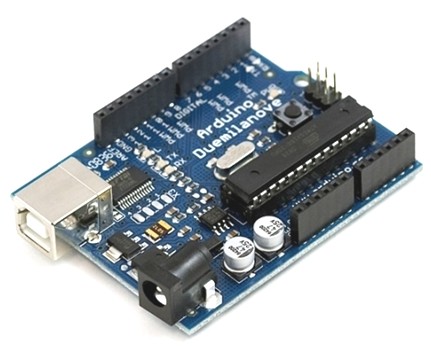
- Arduino Duemilanove module
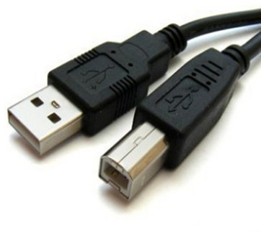
- USB CABLE
Prepare Software
- Arduino 1.0
Download link: Arduino 1.0 Software
- ZG2100BasedWiFiShield’s Library files and code / WiFiShield’s Library files and code
Download link: ZG2100BasedWiFiShield
Download link: WiShield
Programming
Connect to WIFI
- Download file:linksprite-ZG2100BasedWiFiShield-68b2001.zip, unzip it and rename it as ZG2100BasedWiFiShield, then put it under the arduino-1.0\libraries directory.

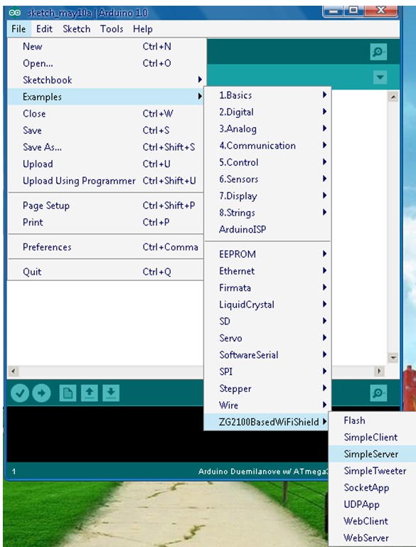
- Open arduino.exe,choose an example such as SimpleServer.
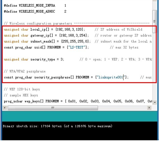
- Change the settings, input the right IP address, default gateway and subnet mask according to your wireless router settings.
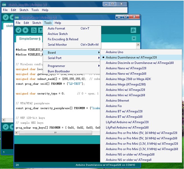
- Choose the right Serial Port and Board.
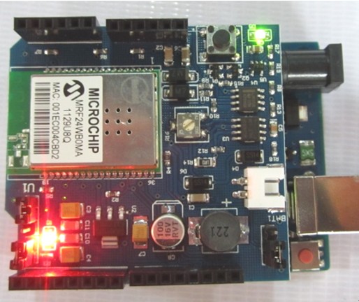
- When Cuhead V2.0 connected to the router through WiFi,the red LED will turn on.
- Input the IP address of Cuhead V2.0 as we set it:192.168.3.120, it showed what SimpleServer is about.(this IP is for demo)
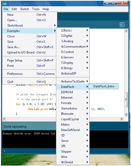
Download the DataFlash
- Download file : linksprite-DataFlash-e90ea99.zip , unzip it and rename it as DataFlash, then put it under the arduino-0022\libraries directory.
- Please note: Using Arduino-0023 and Arduino-0023 the following version, download Data Flash ( DataFlash Download link: DataFlash )
- Open arduino.exe,choose an example such as DataFlash_Intro.
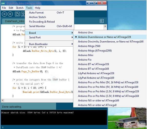
- Choose the right Serial Port and Board.
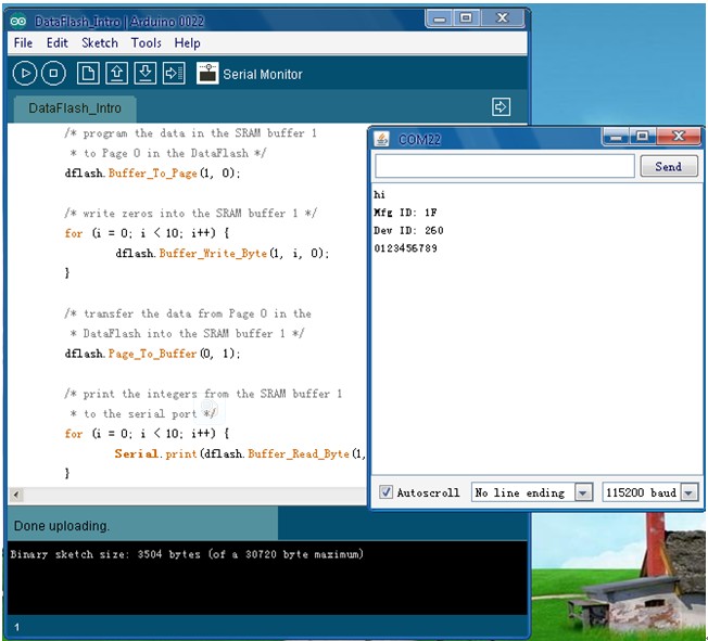
- Click on the Serial Monitor, COM22 window appears information.
FAQ
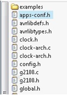
- Q1. Program can't be compiled
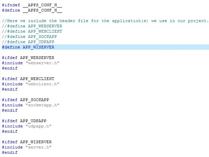
To prevent repeated quotation of the same file, which will cause compile error like duplicate definition and nested quoted. You have to change it here according to your needs. To different examples, the macro definition is different, the default is:
#define APP_WISERVER
If you want to use another example, such as how to use webserver.h,
#define APP_WEBSERVER //#define APP_WISERVER
- Q2. Red LED(D1)not on
- If the program has been downloaded to Arduino, yet red LED(D1)on Cuhead V1.0 is not on, which means Wi-Fi not connected,please check below part. Check the IP address,default gate way and subnet mask in the code if it is right with the WiFi routor settings. And check the SSID,PASSWORD and encryption method. Or you can reset Cuhead V2.0/Arduino module and reconnect them.
Check the jump line parts:
- INTX1, used to choose to interrupt mode, jump line 1, 2 pin is D8, jump line 2, 3 pin is D2. No influence on the use of Cuhead V2.0, not normally use.
- Flash_sn, jump line 1, 2 pin is SS, jump line 2, 3 pin is CS, when you using Wi-Fi choice SS, make Flash invalid.
- Wi-Fi connection indicator light, jump line 1, 2 pin. Cuhead V2.0 leave factory, need to jump line of the part we have adjusted, you can use directly.
Q3. Using UNO R3
A3:When Cuhead V2.0 connected to Arduino UNO R3, Cuhead V2.0 may be unable to connect to wifi.
Note: This issue is only for Arduino R3 of early days. Current version doesn't have this issue anymore.
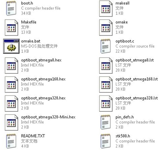
You need to download the latest version of the Bootloader to Arduino microcontroller (ATmegaXXXX).
Open optiboot folder ( X: \ arduino-XXXX \ hardware \ arduino\ bootloaders \ optiboot )
Bootloader (.hex file) download to corresponding version of the Arduino microcontroller (ATmegaXXXX).
Q4.I have your Cuhead module,but when i connect it with my Arduino Mega 2560,it is not working.what can i do now?
A4:Please check the connections with the arduino board carefully,it is different with different arduino boards.
For example,Arduino Mega uses different pins for the SPI interface than the previous boards, so you may not able to use the headers to stack the shield onto the Mega.
And you may have to pull pins to match the correct SPI pins to get it working.
Q5.Does it work with Arduino Uno3 as advertised? Does it use the Arduino WiFi libraries?
It does work with Uno R3. It was having problem with old Uno R2 that has older bootloader.
Q: Thanks for your quick response. The board seems to work great w/ the Uno3.
Most of the examples compile and work; except for the UDP_APP. I'm using the Arduino 1.03 compiler, and I have changed the #define in the app_conf.h file.
I'll keep working through it, but would be like to know if this works for you.
A: For UDP, example, we also need to modify uip-conf.h under libraries\linksprite\WiFiShield.
We need to locate
#define UIP_CONF_UDP 0
change it to:
#define UIP_CONF_UDP 1
Q6. Can CuHead WiFi Shield be used with Arduino Mega?
To make the WiShield work on mega follow the NKC tutorial on wiring up the Ethernet shield http://mcukits.com/2009/04/06/arduino-ethernet-shield-mega-hack/
and make the following changes to spi.h (in hardware\libraries\wishield):
 #define SPI0_SS_BIT                                    BIT0
 ...
 #define SPI0_SCLK_BIT                              BIT1
 ...
 #define SPI0_MOSI_BIT                              BIT2
 ...
 #define SPI0_MISO_BIT                              BIT3
 ...
 #define SPI0_Init()                                    PRR0 = 0x00;\
                                                      DDRB  |= SPI0_SS_BIT|SPI0_SCLK_BIT|SPI0_MOSI_BIT|LEDConn_BIT;\
                                                    DDRB  &= ~SPI0_MISO_BIT;\
                                                    PORTB = SPI0_SS_BIT;\
                                                    SPCR  = 0x50;\
                                                    SPSR  = 0x01
 ...
 #define ZG2100_CS_BIT                              BIT0
 ...
 #define LEDConn_BIT                                      BIT5
the Mega not only remapped the SPI pins, it also remapped the interrupt pins. The ZeroG board triggers an interrupt when it needs the host to do something. This is why the WiShield would init, and then nothing else. If you attach a scope or a LED to the WiShield interrupt pin (pin2/int0), you can see it going low but never getting serviced.
On the Duemilanove, Arduino Pin 2 goes to INT0/PD2 on the ATMega328. On the Mega, Arduino Pin 2 goes to PE4, which is not an interrupt at all.
(1) Bend out pin 2 on the WiShield similar to how pins 10,11,12,13 are bent out.
(2) Jumper this pin on the WiShield to pin 21 on the Arduino Mega.
(3) In "WiServer.cpp" and "WiShield.cpp" change "attachInterrupt(0, zg_isr, LOW);" to "attachInterrupt(2, zg_isr, LOW);". This may be counterintutive, but from the documentation, it seems the Arduino development environment maps interrupt pin 2 to 21. See AttachInterrupt for details.
For extra credit, if you don't like mangling the pins on your beautiful WiShield, connect the jumpers and turn pins 2,10,11,12,13 into high-impedance inputs. Note this means you can't use them for other purposes but they can remain electrically connected.
pinMode(2, INPUT);
pinMode(10, INPUT);
pinMode(11, INPUT);
pinMode(12, INPUT);
pinMode(13, INPUT);
Q7. With this shield can I connect the arduino to my internet router and send instructions from my phone, when I’m at work for example, and say to my arduino to open my air-condition at home?
- Yes. It can.
Support
If you have questions or other better design ideas, you can go to our forum to discuss or creat a ticket for your issue at linksprite support.
Resources
- source code github
- Can CuHead WiFi Shield be used with Arduino Mega?
- Wifi Shield Chip-MRF24WB0MA Datasheet
- User Guide of CuHead
- ZG2100 based Wifi Shield
- datasheet of ZG2100MC
Blogs
- Detailed tutorial on CuHead by CuteDigi
- How to Compile and Test Sample SocketApp of LinkSprite’s CuHead WiFi Shield
- How to Compile Sample UDPApp of LinkSprite’s CuHead WiFi Shield
How to buy
Here to buy CuHead V2.0 on store
See Also
Other related products and resources.
Licensing
This documentation is licensed under the Creative Commons Attribution-ShareAlike License 3.0 Source code and libraries are licensed under GPL/LGPL, see source code files for details.
