Difference between revisions of "4-Digit 7-Segment Module"
Qian.zhang (talk | contribs) (→Software) |
|||
| (2 intermediate revisions by 2 users not shown) | |||
| Line 4: | Line 4: | ||
[[File:LINKER 4D7S 1.jpg]] | [[File:LINKER 4D7S 1.jpg]] | ||
| + | |||
| + | == Features == | ||
| + | |||
| + | Dimensions: 46.2×24.3×14.5mm | ||
| + | |||
| + | Net weight: 7g | ||
| + | |||
| + | == Dimension == | ||
| + | |||
| + | [[File:digital display dimension.jpg]] | ||
==Schematic== | ==Schematic== | ||
| + | |||
| + | *[https://s3.amazonaws.com/linksprite/LinkerKit/4-digitron+SCH.pdf Schematic] | ||
==Sample Code and Setup == | ==Sample Code and Setup == | ||
| Line 27: | Line 39: | ||
[[File:DigitalTube 03.jpg]] | [[File:DigitalTube 03.jpg]] | ||
| + | |||
| + | The running effect is shown below: | ||
| + | |||
| + | [[File:DigitalTube 01.jpg|600px]] | ||
Latest revision as of 02:29, 4 February 2015
Contents
Introduction
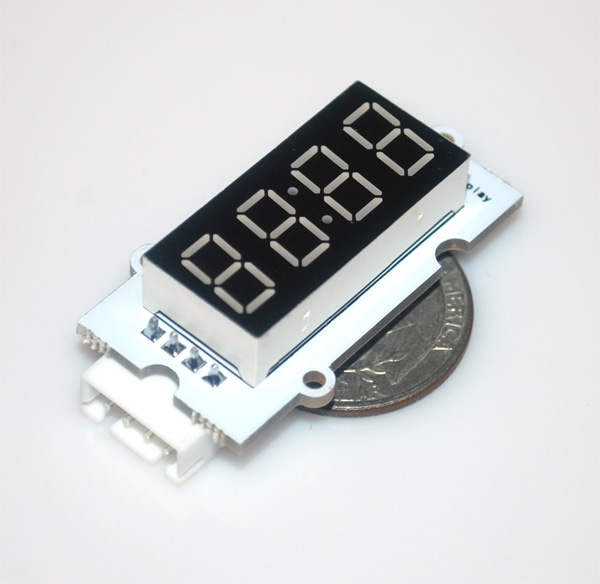
Linker 4-digit 7-segment module uses a chipset of TM1637 to drive a 12-pin 4-digit command anode 7-segment LED. The MCU only needs two GPIO lines to control it.
Features
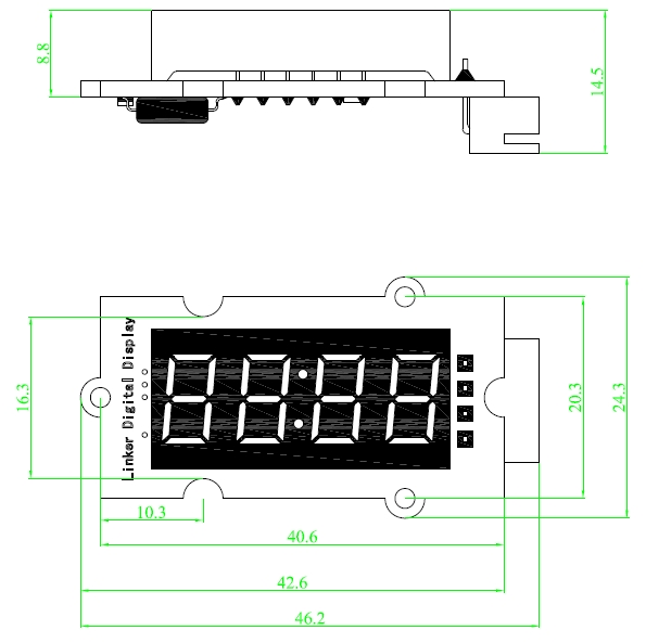
Dimensions: 46.2×24.3×14.5mm
Net weight: 7g
Dimension
Schematic
Sample Code and Setup
Hardware
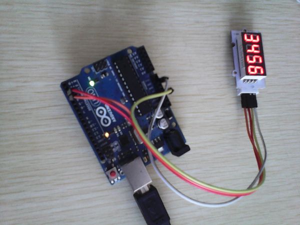
We connect according to the following:
- D2 of Arduino to CLK of Linker 4-digit 7-segment module
- D3 of Arduino to DIO of Linker 4-digit 7-segment module
- +3.3V of Arduino to VCC of Linker 4-digit 7-segment module
- GND of Arduino to GND of Linker 4-digit 7-segment module
Software
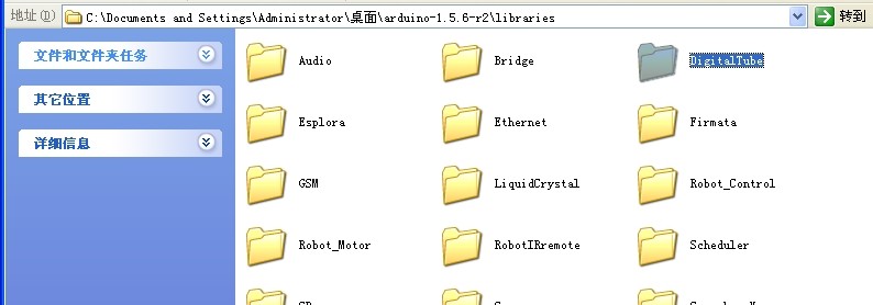
The source files for linker kit is hosted at [ https://github.com/linksprite/Linkerkit/tree/master/Linker_4D7SLED github[. Please download and put under the library path of Arduino IDE, and rename the directory name as DigitalTube as shown below:
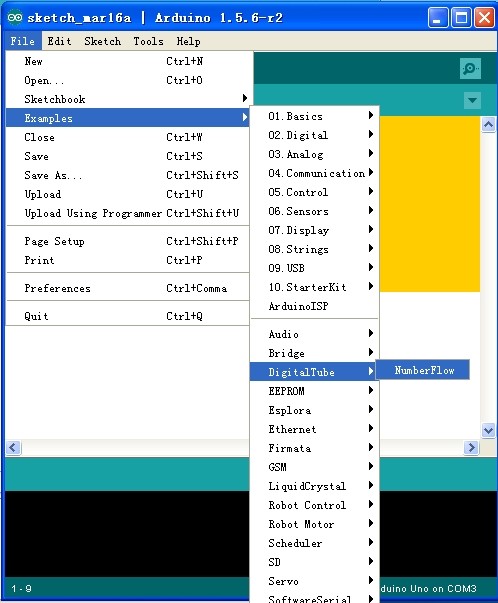
Launch the Arduino IDE and select the example code as below:
The running effect is shown below:
