Difference between revisions of "NFC PN532 Shield"
| (14 intermediate revisions by 4 users not shown) | |||
| Line 14: | Line 14: | ||
NFC operates on unlicensed ISM (Industry Scientific Medical) band of 13.56 MHz Frequency. NFC’s communication range is up to 10 cm. But, this is limited by the antenna and power radiation design. Most devices work within a range of 5mm. NFC shield antenna is designed to work within a range of 1cm. The NFC shield provides all necessary circuitry for PN532 like 27.12Mhz crystal and power supply. It also breaks-out the I/O pins of PN532 for easy access. | NFC operates on unlicensed ISM (Industry Scientific Medical) band of 13.56 MHz Frequency. NFC’s communication range is up to 10 cm. But, this is limited by the antenna and power radiation design. Most devices work within a range of 5mm. NFC shield antenna is designed to work within a range of 1cm. The NFC shield provides all necessary circuitry for PN532 like 27.12Mhz crystal and power supply. It also breaks-out the I/O pins of PN532 for easy access. | ||
| − | The communication between Arduino and the NFC shield is via SPI. | + | The communication between Arduino and the NFC shield is via SPI. |
| + | |||
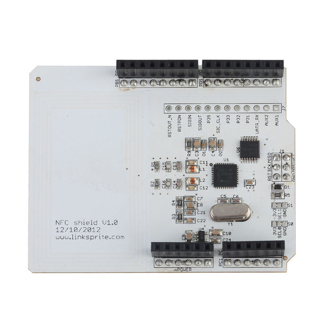
| + | [[File:N01DH WITHOUT PACKAGED FRONT.jpg | 640px]] | ||
| + | |||
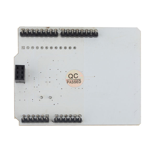
| + | [[File:N01DH WITHOUT PACKAGED BACK1.jpg | 640px]] | ||
| + | |||
| + | |||
| + | == Package List == | ||
| + | *1 X [SHD_RFID_NFCPN532][101101001] | ||
| + | *1 X [RFID_NFC_MIFARE][107201012] | ||
| + | |||
| + | |||
| + | |||
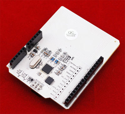
| + | Model: [SHD_RFID_NFCPN532][101101001] | ||
[[File:NFC shield.jpg | 400px]] | [[File:NFC shield.jpg | 400px]] | ||
| + | |||
| + | |||
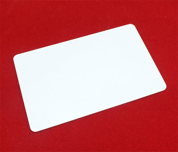
| + | RFID tag, rewritable, Mifare 1, S50 (13.56MHz) included:[RFID_NFC_MIFARE][107201012] | ||
| + | |||
| + | [[File:Mifare.jpg]] | ||
== Features == | == Features == | ||
| Line 417: | Line 435: | ||
== NFC shield application with Android smartphone == | == NFC shield application with Android smartphone == | ||
| + | For this application, the Arduino board used is Arduino ADK. | ||
| + | |||
| + | Please download the project files first [https://s3.amazonaws.com/linksprite/Shields/NFC_shield/NFC+ADK.rar Project files]. | ||
| + | |||
| + | *Copy three directories, Abd, AndroidAccessor and USB_Host_Shield under \NFC ADK\NFC arduino code and libraries to \arduino-1.0.2\libraries\. | ||
| + | *Launch arduino.exe, and select File->Examples->Abd->NFC_ADK to open the sample. | ||
| + | **[[File:NFC Android 1.jpg]] | ||
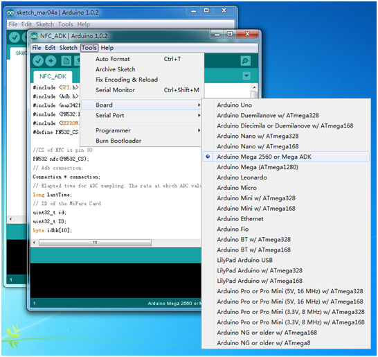
| + | *In menu->tools, select correct port and board as following: | ||
| + | **[[File:NFC Android 2.jpg]] | ||
| + | *Plug NFC shield onto Arduino ADK, and compile and download the sample code to Arduino ADK board. | ||
| − | + | After this, we are done with Arduino part, and let's move onto Android part. | |
| + | Android smartphone part: | ||
| + | *Install NFCadk.apk under \NFC ADK\NFC android code\ to the android device. | ||
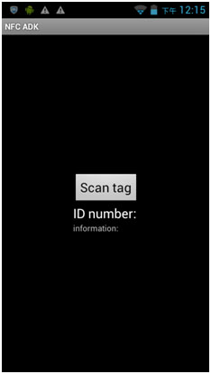
| + | *Launch 'NFC ADK' when the installation is done. | ||
| + | **[[File:NFC Android 3.jpg]] | ||
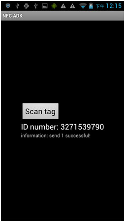
| + | *Click "Scan tag", the ID of the NFC card will be displayed: | ||
| + | **[[File:NFC Android 4.jpg]] | ||
== FAQ == | == FAQ == | ||
| Line 435: | Line 469: | ||
*[https://s3.amazonaws.com/linksprite/Shields/NFC_shield/TXB0104.pdf Datasheet of TXB0104] | *[https://s3.amazonaws.com/linksprite/Shields/NFC_shield/TXB0104.pdf Datasheet of TXB0104] | ||
*[https://s3.amazonaws.com/linksprite/Shields/NFC_shield/PN532_SPI.zip NFC shield Arduino Library V1] | *[https://s3.amazonaws.com/linksprite/Shields/NFC_shield/PN532_SPI.zip NFC shield Arduino Library V1] | ||
| + | *[https://s3.amazonaws.com/linksprite/Shields/NFC_shield/PN532SPI(new).zip NFC shield Arduino data tansfer library] | ||
== How to buy == | == How to buy == | ||
| − | + | Here to buy NFC PN532 Shield on [http://store.linksprite.com/nfc-rfid-pn532-shield-for-arduino-pcduino/ store] | |
| − | |||
| − | |||
| − | |||
== See Also == | == See Also == | ||
Latest revision as of 08:15, 16 September 2015
Contents
Introduction
LinkSprite’s NFC (Near Field Communication) shield is a NFC shield for Arduino built around the popular NXP PN532 integrated circuit.
NFC is a short-distance radio technology that enables communication between devices that are held close to each other.
NFC traces its roots in RFID technology and is an open platform technology standardized in ECMA-340 and ISO/IEC 18092.
NFC is widely used similar to RFID to recognize cards/tags (NXP Mifare cards /tags). NFC can be used as an alternative to Travelcard using the read/write memory provided in cards/tags.
Few mobile phones come with built-in NFC - they are used as readers of cards, tags, smart posters with a web URL (like a mobile QR-code reader). This technology is also being applied in smart cashless purchases.
Like many other standards, NFC technology is regulated by the NFC which standardizes NFC communication - how the devices pair, share data and allow a secure transaction to happen. The NFC Forum develops and certifies devices compliant with the NFC standards.
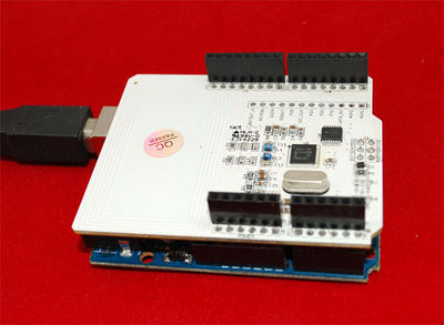
NFC operates on unlicensed ISM (Industry Scientific Medical) band of 13.56 MHz Frequency. NFC’s communication range is up to 10 cm. But, this is limited by the antenna and power radiation design. Most devices work within a range of 5mm. NFC shield antenna is designed to work within a range of 1cm. The NFC shield provides all necessary circuitry for PN532 like 27.12Mhz crystal and power supply. It also breaks-out the I/O pins of PN532 for easy access.
The communication between Arduino and the NFC shield is via SPI.
Package List
- 1 X [SHD_RFID_NFCPN532][101101001]
- 1 X [RFID_NFC_MIFARE][107201012]
Model: [SHD_RFID_NFCPN532][101101001]
RFID tag, rewritable, Mifare 1, S50 (13.56MHz) included:[RFID_NFC_MIFARE][107201012]
Features
- Compatible with Arduino shield. No soldering required.
- SPI interface. Hence, most Arduino pins are available for other applications.
- Built in PCB Antenna.
- Supports both 3.3V and 5V operation using TI's TXB0104 level translator.
- Socket to connect with other shields.
- The maximum communication range of this NFC shield is about 5 cm.
- Not being able to read/write Mifare’s Ultralight C chip, only to read it’s ID.
Application Ideas
- Use as a RFID reader with Mifare One tags (ISO14443 Type-A) and cards (13.56 MHZ).
- Build visiting card sharing systems.
- Build attendance systems.
- Design authentication systems.
- Read Smart Posters.
- Securely exchange small data with other NFC devices.
- Use with Arduino ADK Main Board for creating mobile NFC applications.
- Many other applications.
Cautions
Schematic
Specification
| Item | Min | Typical | Max | Unit |
|---|---|---|---|---|
| Voltage | 4.3 | 5.0 | 5.7 | V |
| Current | 80.0 | 90.0 | 100.0 | mA |
| Maximum Communication Distance | 2.9 | cm | ||
| Dimension | 69.1x55.7x17.8 | mm | ||
| Supported Card Type | Mifare One | / | ||
| Net Weight | 18.5 | g | ||
Application Programming Interfaces
NFC is a secure technology (meaning the communication between NFC reader/writer and NFC card/tag happens in an encrypted and authenticated manner). The security and other complex handshaking are handled by PN532 firmware provided by NXP.
The APIs make use of the commands to invoke the interfaces provided by PN532 firmware via SPI. All these commands are documented in PN532 User Manual. The following APIs are provided in PN532 library.
- PN532(uint8_t cs, uint8_t clk, uint8_t mosi, uint8_t miso)
An object of PN532() is created with this function. The digital SPI pins of Arduino (in AtMega328P or Mega) are specified as parameters.
Usage
<syntaxhighlight lang=c>
- define SCK 13
- define MOSI 11
- define SS 10
- define MISO 12
PN532 nfc(SCK, MISO, MOSI, SS); </syntaxhighlight>
- Begin()
begin() is called to initialize the driver.
Usage
<syntaxhighlight lang=c> nfc.begin(); </syntaxhighlight>
- boolean SAMConfig(void)
This API invokes the SAMConfiguration command of PN532 and sets it to normal mode, where SAM stands for Security Access Module (i.e the PN532 system). The PN532 system can work in normal mode, virtual card mode, wired card mode and dual card mode.
Usage
<syntaxhighlight lang=c> nfc.SAMConfig(); // Call this before any read/write operation </syntaxhighlight>
- uint32_t readPassiveTargetID(uint8_t cardbaudrate)
This function reads the passive target ID and returns it as a 32-bit number. At the moment only reading Mifare ISO14443A cards/tags are supported. Hence use PN532_MIFARE_ISO14443A as parameter. It returns a 32 bit card number.
Usage
<syntaxhighlight lang=c> uint32_t cid; // look for MiFare type cards/tags cid = nfc.readPassiveTargetID(PN532_MIFARE_ISO14443A); </syntaxhighlight>
- uint32_t authenticateBlock(uint8_t cardnumber, uint32_t cid, uint8_t blockaddress ,uint8_t authtype, uint8_t * keys)
This function is used to authenticate a memory block with key before read/write operation. It returns true when successful.
- cardnumber can be 1 or 2
- cid is the 32-bit card ID.
- blockaddress is the block number (any number between 0 - 63 for Mifare card).
- authtype is which key is to be used for authentication (either KEY_A or KEY_B).
- keys is a pointer to the byte-array holding the 6 keys.
Usage
<syntaxhighlight lang=c> uint8_t keys[]= {0xFF,0xFF,0xFF,0xFF,0xFF,0xFF}; // default key of a fresh card nfc.authenticateBlock(1, id ,3,KEY_A,keys); ////authenticate block 3, id is 32-bit passive target id. </syntaxhighlight>
- uint32_t readMemoryBlock(uint8_t cardnumber,uint8_t blockaddress, uint8_t * block)
This function reads a memory block after authentication with the key. It returns true when successful.
- cardnumber can be 1 or 2
- blockaddress is the block number (any number between 0 - 63 for Mifare card) to read. Each block is 16-byte long for Mifare standard card.
- block is a pointer to a byte-array holding the 16-byte block data.
Usage
<syntaxhighlight lang=c> uint8_t block[16]; nfc.readMemoryBlock(1,3,block); //Read can be performed only when authentication was successful. </syntaxhighlight>
- uint32_t writeMemoryBlock(uint8_t cardnumber,uint8_t blockaddress, uint8_t * block)
This function writes data to a memory block after authentication with the key. It returns true when successful.
- cardnumber can be 1 or 2
- blockaddress is the block number (any number between 0 - 63 for Mifare card) to write. Each block is 16-byte long for Mifare standard card.
- block is the pointer to a byte-array holding the 16-bytes block-data to write.
Usage
<syntaxhighlight lang=c> uint8_t writeBuffer[16];
   for(uint8_t ii=0;ii<16;ii++)
    {
      writeBuffer[ii]=ii; //Fill buffer with 0,1,2....F
    }
nfc.writeMemoryBlock(1,0x08,writeBuffer); /* Write writeBuffer[] to block address 0x08. Read can be performed only when authentication was successful. */
</syntaxhighlight>
- uint32_t PN532::configurePeerAsInitiator(uint8_t baudrate)
This function implements a peer to peer initiator. It returns true when successful.
- baudrate can be any number from 0-2, 0 for 106kbps , 1 for 201kbps or 2 for 424kbps. At this moment only 1 and 2 are supported.
Note: This is an experimental feature. It supports NFC peer to peer communication with other NFC shields. Interaction with mobile device is not tested.
Usage
<syntaxhighlight lang=c> // Configure PN532 as Peer to Peer Initiator if( nfc.configurePeerAsInitiator(2) ) //if connection is error-free
   {
    //Your Send  Receive code here
   }
</syntaxhighlight>
- uint32_t configurePeerAsTarget()
This function implements a peer to peer target. It returns true when successful.
Note: This is an experimental feature. It supports NFC peer to peer communication with other NFC shields. Interaction with mobile device is not tested.
Usage
<syntaxhighlight lang=c> // Configure PN532 as Peer to Peer Target if(nfc.configurePeerAsTarget()) //if connection is error-free
  {
       //You code to trans-receive data
  }
</syntaxhighlight>
- uint32_t initiatorTxRx(char *DataOut,char *DataIn)
This function is used to transmit and receive data to and from the target. This code is used by the NFC peer to peer initiator. It returns true when successful.
- DataOut is a pointer to a 16-byte long array of char to be transmitted.
- DataIn is a pointer to a 16-byte long array of chars being received.
Note: This is an experimental feature. It supports NFC peer to peer communication with other NFC shields. Interaction with mobile device is not tested.
Usage
<syntaxhighlight lang=c>
   // Configure PN532 as peer to peer Initiator in active mode
   if( nfc.configurePeerAsInitiator(2) ) //if connection is error-free
   {
       //transmit-receive data
       if(nfc.initiatorTxRx(DataOut,DataIn))
       {
        Serial.print("Data Sent and Received: ");
        Serial.println(DataIn);
       }
   }
</syntaxhighlight>
- uint32_t targetTxRx(char *DataOut,char *DataIn)
This function is used to transmit and receive data to and from the initiator. This code is used by the NFC peer to peer target to respond to the initiator. It returns true when successful.
- DataOut is a pointer to a 16-byte long array of char to be transmitted.
- DataIn is a pointer to a 16-byte long array of chars being received.
Usage
<syntaxhighlight lang=c>
  // Configure PN532 as peer to peer target
   if(nfc.configurePeerAsTarget()) //if connection is error-free
   {
       //trans-receive data
       if(nfc.targetTxRx(DataOut,DataIn))
       {
        Serial.print("Data Received: ");
        Serial.println(DataIn);
       }
   }
</syntaxhighlight>
Note: This is an experimental feature. It supports NFC peer to peer communication with other NFC shields. Interaction with mobile device is not tested.
Mechanic Dimensions
Usage
Hardware Installation
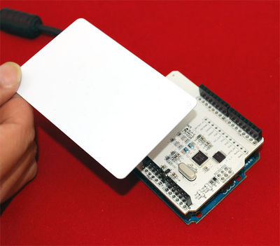
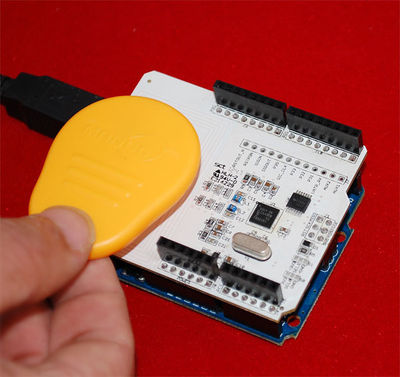
- Connect the NFC shield to Arduino as shown below.
- Compile and upload the example sketch provided.
- Hold the Mifare card near the antenna. The NFC shield will read the passive ID data.
- Hold the Mifare tag near the antenna. The NFC shield will read the passive ID data.
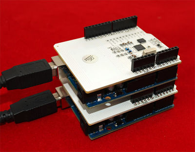
- Use the following setup for establishing peer to peer communication between two Arduinos using two NFC shields.
Programming
The PN532 software library for the NFC shield is derived from the PN532 library. The original library provides API for reading passive target ID of Mifare card/tags. This is enough for card/tag identification purpose. We have added APIs for authentication, reading from and writing to Mifare cards/tags. The software library only provides low level functionality for demonstration. Users need to implement their own NFC application layer (if required).
Please note: Arduino 1.0 users have to change the #include <WProgram.h> lines to #include <Arduino.h> in PN532.cpp and PN532.h.
Quick Start Demo
A simple sketch is provided herein to read the passive target ID of Mifare cards and tags. Passive target ID is a unique, permanent and read-only number programmed on to the Mifare card by the manufacturer.
This number is used to identify one card from another.
- Connect the NFC shield to Arduino / Arduino as shown above.
- Compile and upload the program to Arduino.
- Bring a Mifare card near the NFC antenna as shown above.
<syntaxhighlight lang=c>
- include <PN532.h>
- define SS 10
- if defined(__AVR_ATmega1280__) || defined(__AVR_ATmega2560__)
 #define MISO 50
 #define MOSI 51
 #define SCK 52
- else
 #define MISO 12
 #define MOSI 11
 #define SCK 13
- endif
PN532 nfc(SCK, MISO, MOSI, SS);
void setup(void) {
 Serial.begin(9600);
 nfc.begin();

 uint32_t versiondata = nfc.getFirmwareVersion();
 if (! versiondata) {
   Serial.print("Didn't find PN53x board");
   while (1); // halt
 }
 // Got ok data, print it out!
 Serial.print("Found chip PN5"); Serial.println((versiondata>>24) & 0xFF, HEX);
 Serial.print("Firmware ver. "); Serial.print((versiondata>>16) & 0xFF, DEC);
 Serial.print('.'); Serial.println((versiondata>>8) & 0xFF, DEC);
 Serial.print("Supports "); Serial.println(versiondata & 0xFF, HEX);

 // configure board to read RFID tags and cards
 nfc.SAMConfig();
}
void loop(void) {
 uint32_t id;
 // look for MiFare type cards
 id = nfc.readPassiveTargetID(PN532_MIFARE_ISO14443A);

 if (id != 0) {
   Serial.print("Read card #"); Serial.println(id);
 }
} </syntaxhighlight>
Demo 1: readAllMemoryBlocks.ino
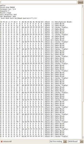
Compile and upload readAllMemoryBlocks.pde example provided in the library. This sketch reads the complete memory of a Mifare standard card using default authentication keys. The output gives typical memory layout of fresh Mifare standard card.
Blocks are classified as manufacturer block (read-only), data block (user/application writable area), and sector trailer (authentication and access bits for that sector).
Output
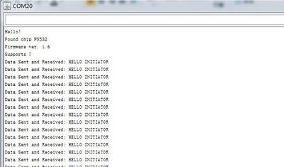
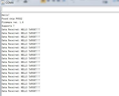
Demo 2: PtoPInitiator.pde and PtoPTarget.ino
An experimental NFC peer to peer communication is implemented in the latest NFC library. This uses an active initiator for peer to peer communication.
- Load the two sketches in two different Arduinos with NFC shields.
- Place the two shields close to each other. See hardware setup above.
- Open the serial terminal and observe the data transmitted and received.
Outout
- P2P Initiator
- P2P Target
NFC shield application with Android smartphone
For this application, the Arduino board used is Arduino ADK.
Please download the project files first Project files.
- Copy three directories, Abd, AndroidAccessor and USB_Host_Shield under \NFC ADK\NFC arduino code and libraries to \arduino-1.0.2\libraries\.
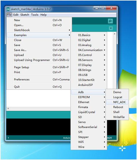
- Launch arduino.exe, and select File->Examples->Abd->NFC_ADK to open the sample.
- In menu->tools, select correct port and board as following:
- Plug NFC shield onto Arduino ADK, and compile and download the sample code to Arduino ADK board.
After this, we are done with Arduino part, and let's move onto Android part.
Android smartphone part:
- Install NFCadk.apk under \NFC ADK\NFC android code\ to the android device.
- Launch 'NFC ADK' when the installation is done.
- Click "Scan tag", the ID of the NFC card will be displayed:
FAQ
Please list your question here:
Support
If you have questions or other better design ideas, you can go to our forum to discuss or creat a ticket for your issue at linksprite support.
Resources
- PN532 IC Datasheet
- PN532 IC User Manual
- Datasheet of MIC5205_3.3
- Datasheet of TXB0104
- NFC shield Arduino Library V1
- NFC shield Arduino data tansfer library
How to buy
Here to buy NFC PN532 Shield on store
See Also
Other related products and resources.
Licensing
This documentation is licensed under the Creative Commons Attribution-ShareAlike License 3.0 Source code and libraries are licensed under GPL/LGPL, see source code files for details.
