Difference between revisions of "Hall Effect Sensor"
(→Example Project) |
|||
| Line 36: | Line 36: | ||
|} | |} | ||
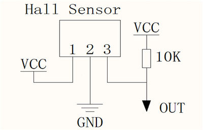
| + | '''Schematics:''' | ||
| + | |||
| + | [[File:Hall sensor sch.jpg | 400px]] | ||
==Resources== | ==Resources== | ||
*[https://s3.amazonaws.com/linksprite/Arduino_kits/SensorsPack/0004824_US5881_rev008.pdf Datasheet] | *[https://s3.amazonaws.com/linksprite/Arduino_kits/SensorsPack/0004824_US5881_rev008.pdf Datasheet] | ||
Revision as of 07:33, 30 November 2012
Hall effect sensors detect whether a magnet is near. Useful for non-contact/waterproof type switches, position sensors, rotary/shaft encoders.
Runs at 3.5V up to 24V. To use connect power to pin 1 (all the way to the left), ground to pin 2 (middle) and then a 10K pull up resistor from pin 3 to power. Then listen on pin 3, when the south pole of a magnet is near the front of the sensor, pin 3 will go down to 0V. Otherwise it will stay at whatever the pullup resistor is connected to. Nothing occurs if a magnet's north pole is nearby (unipolar).
Example Project
The purpose of this project is to demo the usage of Hall Sensor. When the magnet is close to Hall sensor, the LED-L on Arduino will turn on, and the LED will turn on when the magnet is removed.
List of Components:
| Item | Quantity |
|---|---|
| Arduino Duemilanove or Uno | 1 |
| Hall Sensor | 1 |
| USB Cable with type A Interface | 1 |
| Mini Breadboard | 1 |
| Jumper Wire with Male Header | 3 |
| Resister with value 10K ohm | 1 |
| PC | 1 |
Schematics:
