Difference between revisions of "ATWIN Quad-band GPRS/GSM Shield for Arduino"
Katherine.d (talk | contribs) (→Resources) |
(→Features) |
||
| (60 intermediate revisions by 7 users not shown) | |||
| Line 1: | Line 1: | ||
== Introduction == | == Introduction == | ||
| − | |||
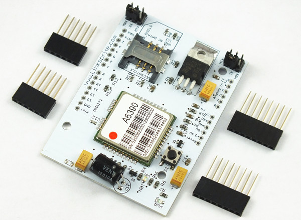
| − | + | This LinkSprite ATWIN Quad-band GPRS/GSM shield has PCB etched antenna, so no need for external antenna. | |
| − | + | ATWIN Quad-band GPRS/GSM shield is an ultra compact and high quality wireless module base on infineon UCL2 platform with industy-standard interface. | |
| + | This is a SMT package with small dimension, low power consumption, quad-band (AT139) and dual-band (AT139D) GSM/GPRS module. | ||
| − | + | It can provide with voice, SMS, Fax, data applicationgs for customers. | |
| + | |||
| + | '''[http://v.youku.com/v_show/id_XMzkyOTMyMTQ0.html Video Introduction]''' | ||
| + | |||
| + | |||
| + | [[File:600PX-ATWIN.jpg]] | ||
== Features == | == Features == | ||
| + | {| class="wikitable" | ||
| + | |||
| + | ! Features | ||
| + | ! colspan=2 align="center"| Description | ||
| + | |||
| + | |- style="background:silver; color:black" | ||
| + | |||
| + | | width="200px" align="center"| Network | ||
| + | | colspan=2 align="center"| GSM/GPRS | ||
| + | |||
| + | |- | ||
| + | |||
| + | | width="200px" align="center"| Frequency Bands | ||
| + | | width="300px" align="center"| AT139:GSM850/GSM900/DCS1800/PCS1900MHz | ||
| + | | width="300px" align="center"| AT139D:GSM900/DCS1800MHz | ||
| + | |||
| + | |- | ||
| + | |||
| + | | width="200px" align="center"| RF Output Power | ||
| + | | width="300px" align="center"| AT139:GSM850/GSM900: 33dBm, DCS1800/PCS1900:30dBm | ||
| + | | width="300px" align="center"| AT139D:GSM900:33dBm, DCS1800:30dBm | ||
| + | |||
| + | |- | ||
| + | |||
| + | | width="200px" align="center"| RF Receive Sensitivity | ||
| + | | colspan=2 align="center"| <-108dBm | ||
| + | |||
| + | |- | ||
| + | |||
| + | | width="200px" align="center"| Speech codec modes | ||
| + | | colspan=2 align="center"| FR,EFR,HR,AMR | ||
| + | |||
| + | |- | ||
| + | |||
| + | | width="200px" align="center"| SMS | ||
| + | | colspan=2 align="center"| TEXT/PDU | ||
| + | |- | ||
| − | == Application | + | | width="200px" align="center"| GPRS Connectivity |
| + | | colspan=2 align="center"| GPRS Class 10 | ||
| + | |||
| + | |- | ||
| + | |||
| + | | | ||
| + | | colspan=2 align="center"| Coding Scheme:CS1,CS2,CS3,CS4 | ||
| + | |||
| + | |- style="background:silver; color:black" | ||
| + | |||
| + | | width="200px" align="center"| Physical Characteristics | ||
| + | | colspan=2| | ||
| + | |||
| + | |- | ||
| + | |||
| + | | width="200px" align="center"| Package | ||
| + | | colspan=2 align="center"| SMT | ||
| + | |||
| + | |- | ||
| + | |||
| + | | width="200px" align="center"| Dimensions | ||
| + | | colspan=2 align="center"| 24(±0.1)*24(±0.1)*3(±0.1)mm | ||
| + | |||
| + | |- | ||
| + | |||
| + | | width="200px" align="center"| Weight | ||
| + | | colspan=2 align="center"| 4g | ||
| + | |||
| + | |- style="background:silver; color:black" | ||
| + | |||
| + | | width="200px" align="center"| Performance | ||
| + | | colspan=2| | ||
| + | |||
| + | |- | ||
| + | | width="200px" align="center"| Power Supply | ||
| + | | colspan=2 align="center"| 3.3V~4.5V | ||
| + | |||
| + | |- | ||
| + | | width="200px" align="center"| Antenna | ||
| + | | colspan=2 align="center"| External Antenna | ||
| + | |||
| + | |- | ||
| + | | width="200px" align="center"| MCP | ||
| + | | colspan=2 align="center"| 64Mb NOR + 32Mb PSRAM | ||
| + | |||
| + | |- | ||
| + | | width="200px" align="center"| Audio | ||
| + | | colspan=2 align="center"| Two input/output Audio channels | ||
| + | |||
| + | |- | ||
| + | | width="200px" align="center"| SIM Card Application | ||
| + | | colspan=2 align="center"| Support SIM Card:1.8V/3.0V | ||
| + | |||
| + | |- | ||
| + | | width="200px" align="center"| Pin Amounts | ||
| + | | colspan=2 align="center"| 38 PINs | ||
| + | |||
| + | |- style="background:silver; color:black" | ||
| + | |||
| + | | width="200px" align="center"| Firmware | ||
| + | | colspan=2| | ||
| + | |||
| + | |- | ||
| + | | width="200px" align="center"| Operating System | ||
| + | | colspan=2 align="center"| OSE | ||
| + | |||
| + | |} | ||
== Cautions == | == Cautions == | ||
| Line 20: | Line 128: | ||
== Schematic == | == Schematic == | ||
| − | *[ | + | *[https://s3.amazonaws.com/linksprite/Shields/ATWIN/schematic_of_ATWIN.rar ATWIN Quad-band GPRS/GSM shield Schematic] |
| − | |||
| − | |||
| − | |||
| − | |||
| − | |||
| − | |||
== Usage == | == Usage == | ||
| Line 33: | Line 135: | ||
=== Hardware Installation === | === Hardware Installation === | ||
| − | The shield must be powered by a wall adapter with | + | '''First Tutorial''' |
| + | The shield must be powered by a wall adapter with 9V, 1A, like this one: [http://www.cutedigi.com/tools/power-supply/wall-adapter-power-supply-9vdc-1a.html PW-9VDC-1A_X3] | ||
*RX jump to MRX, TX jump to MTX, and remove the atmega328P from arduino. By doing this, we can directly monitor serial port output using the USB port.The default baud rate is 115200. | *RX jump to MRX, TX jump to MTX, and remove the atmega328P from arduino. By doing this, we can directly monitor serial port output using the USB port.The default baud rate is 115200. | ||
*Install X-CTU serial terminal console:[http://www.cutedigi.com/pub/software/setup_xctu_5100.exe setup_xctu_5100.exe] | *Install X-CTU serial terminal console:[http://www.cutedigi.com/pub/software/setup_xctu_5100.exe setup_xctu_5100.exe] | ||
| + | |||
| + | |||
| + | '''Second Tutorial''' | ||
*Now we are going to use atmega328P's UART to talk to USB, and soft serial of atmega328P to talk to ATWIN. | *Now we are going to use atmega328P's UART to talk to USB, and soft serial of atmega328P to talk to ATWIN. | ||
| − | *Before we do that, we have to change ATWIN's data rate to 9600 as soft serial can't go to | + | *Before we do that, we have to change ATWIN's data rate to 9600 as soft serial can't go to 115200.In first tutorial setup, do: AT+IPR=9600 to set the baud rate to 9600 |
| + | |||
| + | *Now set the jumper RX to D3, and TX to D2. SO that atmega328P's UART to talk to USB and soft serial of atmega328P to talk to ATWIN. | ||
| + | |||
| + | === Programming === | ||
| − | + | <syntaxhighlight lang="c"> | |
| − | |||
| − | |||
| − | |||
#include //Include the NewSoftSerial library to send serial commands to the cellular module. | #include //Include the NewSoftSerial library to send serial commands to the cellular module. | ||
#include //Used for string manipulations | #include //Used for string manipulations | ||
| Line 75: | Line 182: | ||
} | } | ||
| − | </ | + | </syntaxhighlight> |
| + | |||
| + | '''AT Command Tester Application''' | ||
| + | |||
| + | [http://m2msupport.net/m2msupport/module-tester/ AT Command Tester] is a free online tool test [http://m2msupport.net/m2msupport/software-and-at-commands-for-m2m-modules/ AT Commands] and other modem functionalities of [http://m2msupport.net/m2msupport/category/devices/gprs-modem/ 2G modules] (GPRS/EDGE) , [http://m2msupport.net/m2msupport/category/devices/gprs-modem/ 3G Modules] (HSDPA/EVDO) and [http://m2msupport.net/m2msupport/search-page/?Max!Download!Speed=100%20Mbps 4G Modules] (LTE).AT Command Tester tool connects to the modem port of the device and can test various modem functions such as getting [http://m2msupport.net/m2msupport/at-commands-to-get-device-information/ device information], [http://m2msupport.net/m2msupport/data-call-at-commands-to-set-up-gprsedgeumtslte-data-call/ gprs data call], [http://m2msupport.net/m2msupport/voice-call-at-commands-to-set-up-voice-call/ voice call],[http://m2msupport.net/m2msupport/at-command-for-http-functions-for-remote-server-data-access/ http access], [http://m2msupport.net/m2msupport/signal-quality/ checking signal condition], [http://m2msupport.net/m2msupport/network-registration/ network registration], [http://m2msupport.net/m2msupport/sms-at-commands/ SMS functions], [http://m2msupport.net/m2msupport/sim-at-commands-for-sim-presense-and-status/ SIM access], [http://m2msupport.net/m2msupport/sim-phonebook-at-commands/ phonebook functions] etc. | ||
| + | |||
| + | In the 'Port Configuration' section of the tool, users can search for available ports using the 'Find Ports' button. Then using the 'Connect' button, users can connect to the modem port of the device. | ||
| + | |||
| + | In the 'Command Mode' tab of AT Command Tester, single AT commands can be sent. The drop down list provides AT command description and examples. Users can modify the default command settings. | ||
| + | |||
| + | [[File:M2m img1.PNG]] | ||
| + | |||
| + | |||
| + | Under the 'Script Mode' tab, multiple AT commands can be sent at a time. Users can add descriptive comments and save the script on their local machine. | ||
| + | |||
| + | [[File:Script mode.PNG]] | ||
| + | |||
| + | Data Call | ||
| + | |||
| + | To make a data call with the modem, you need to connect to the APN of the carrier network. The carrier APN and other required information are stored in the SIM card and are referred as PDP contexts. Typically multiple PDP contexts are stored in the SIM for different call types. With the AT Command Tester you can edit/add/delete PDP contexts in a easy to use user interface. | ||
| + | |||
| + | [[Image:Datacall.PNG]] | ||
| + | |||
| + | |||
| + | <br>Typical call setup sequence, | ||
| + | |||
| + | [http://m2msupport.net/m2msupport/atcgdcont-define-pdp-context/ AT+CGDCONT?] | ||
| + | |||
| + | +CGDCONT: 1,"IP","epc.tmobile.com","0.0.0.0",0,0<br>+CGDCONT: 2,"IP","test5","0.0.0.0",0,0<br>+CGDCONT: 3,"IP","","0.0.0.0",0,0 | ||
| + | |||
| + | OK<br>Checking registration status... | ||
| + | |||
| + | [http://m2msupport.net/m2msupport/atcreg-network-registration/ AT+CREG?] | ||
| + | |||
| + | +CREG: 0,1 | ||
| + | |||
| + | OK<br>The device is registered in home network. | ||
| + | |||
| + | Checking if device is already connected... | ||
| + | |||
| + | [http://m2msupport.net/m2msupport/atcgact-pdp-context-activate-or-deactivate/ AT+CGACT?] | ||
| + | |||
| + | +CGACT: 1,0<br>+CGACT: 2,0<br>+CGACT: 3,0 | ||
| + | |||
| + | OK<br>[http://m2msupport.net/m2msupport/atcmee-report-mobile-termination-error/ AT+CMEE=1] | ||
| + | |||
| + | OK<br>Attaching to network...<br>AT+CGATT=1 | ||
| + | |||
| + | OK | ||
| + | |||
| + | Connecting... | ||
| + | |||
| + | [http://m2msupport.net/m2msupport/atcgact-pdp-context-activate-or-deactivate/ AT+CGACT=1, 1] | ||
| + | |||
| + | OK<br>Connect Sucessful | ||
| + | |||
| + | <br> '''SMS''' | ||
| + | |||
| + | The SMS tab of the 'AT Command Tester' tool provides the interfaces to send SMS messages. You can also list/view/delete SMS messages stored on the SIM. | ||
| + | |||
| + | [[Image:Sms.PNG]] <br> General sequence for sending SMS message, | ||
| + | |||
| + | Checking registration status... | ||
| + | |||
| + | [http://m2msupport.net/m2msupport/atcreg-network-registration/ AT+CREG?] | ||
| + | |||
| + | +CREG: 0,1 | ||
| + | |||
| + | OK<br>The device is registered in home network. | ||
| + | |||
| + | AT+CMGS="858XXXXXXX" | ||
| + | |||
| + | > Test Message with AT Command Tester� | ||
| + | |||
| + | +CMGS: 19 | ||
| + | |||
| + | OK<br>SMS Send successful | ||
| + | |||
| + | '''Network Selection''' - This tab allows the user to manually select available networks. Modems are typically set for automatic network selection. 'Find Networks' button will command the modem to scan for available networks. | ||
| + | |||
| + | [[Image:Network selection.PNG]] | ||
| + | |||
| + | <br> | ||
| + | |||
| + | AT+COPS command will initiate network scan in the modem, | ||
| + | |||
| + | Finding Networks. Please wait.. | ||
| + | |||
| + | [http://m2msupport.net/m2msupport/atcops-plmn-selection/ AT+COPS=?] | ||
| + | |||
| + | +COPS: (2,"T-Mobile","T-Mobile","310260"),(1,"AT&T","AT&T","310410"),,(0,1,4),(0,1,2) | ||
| + | |||
| + | OK<br>Networks found | ||
| + | |||
| + | <br> | ||
| + | |||
| + | '''Phonebook'''<br> | ||
| + | |||
| + | With the 'Phone Book' tab, you can add/delete/read phone book entries stored on the SIM, | ||
| + | |||
| + | [[Image:Phone book.PNG]] | ||
| + | |||
| + | Getting phonebook entries.. | ||
| + | |||
| + | [http://m2msupport.net/m2msupport/atcpbr-read-phonebook-entries/ AT+CPBR=1,99] | ||
| + | |||
| + | +CPBR: 1,"*233",129,"Refill Now" | ||
| + | |||
| + | +CPBR: 2,"#999#",255,"Check Balance" | ||
| + | |||
| + | +CPBR: 3,"8878878878",129,"Test" | ||
| + | |||
| + | OK<br> | ||
| + | |||
| + | == Example Project == | ||
| + | |||
| + | === Send SMS === | ||
| + | |||
| + | For this project, the following is the jumper setting: | ||
| + | *TX-> MRX | ||
| + | *RX->MTX | ||
| + | *Please remove the USB cable after downloading the program | ||
| + | |||
| + | <syntaxhighlight lang="c"> | ||
| + | |||
| + | char str1[]={'A','T','+','C','S','C','S','=','"','G','S','M','"'}; | ||
| + | char str2[]={'A','T','+','C','M','G','S','=','"','1','5','9','7','2','1','6','9','1','8','9','"'}; | ||
| + | int i; | ||
| + | char inByte = 0; | ||
| + | //unsigned char receive_ACK[6]; | ||
| + | char hex1[]={0x1A}; | ||
| + | void setup() | ||
| + | { | ||
| + | // start serial port at 9600 bps and wait for port to open: | ||
| + | Serial.begin(9600); | ||
| + | //while (!Serial) { | ||
| + | ; // wait for serial port to connect. Needed for Leonardo only | ||
| + | // } | ||
| + | delay(8000); | ||
| + | Serial.println(); | ||
| + | for(i=10;i>0;i--) | ||
| + | {delay(500); | ||
| + | Serial.println("AT");} | ||
| + | |||
| + | delay(1000); | ||
| + | Serial.println("AT"); | ||
| + | delay(1000); | ||
| + | for(i=0;i<13;i++) | ||
| + | Serial.print(str1[i]); | ||
| + | Serial.println(); | ||
| + | delay(1000); | ||
| + | Serial.println("AT+CMGF=1"); | ||
| + | delay(1000); | ||
| + | for(i=0;i<21;i++) | ||
| + | Serial.print(str2[i]);//AT+CMGS="15972169189" | ||
| + | Serial.println(); | ||
| + | delay(1000); | ||
| + | Serial.print("HELLO Sir,Thank you very much fit my test!"); | ||
| + | delay(1000); | ||
| + | Serial.print(hex1); | ||
| + | delay(1000); | ||
| + | |||
| + | } | ||
| + | |||
| + | void loop() | ||
| + | { /* | ||
| + | Serial.println("AT"); delay(500); | ||
| + | if (Serial.available() > 0) { | ||
| + | // get incoming byte: | ||
| + | inByte = Serial.read(); | ||
| + | Serial.println(inByte); | ||
| + | } | ||
| + | */ | ||
| + | } | ||
| + | |||
| + | </syntaxhighlight> | ||
| + | ===Detect an event and send SMS to a cell phone number stored in SD card, and display alarm in 8X8 LED matrix=== | ||
| − | === | + | <syntaxhighlight lang="c"> |
| + | |||
| + | #include <SD.h> | ||
| + | char str1[]={'A','T','+','C','S','C','S','=','"','G','S','M','"'}; | ||
| + | //char str2[]={'A','T','+','C','M','G','S','=','"','1','5','9','7','2','1','6','9','1','8','9','"'}; | ||
| + | char hex[]={0x1A}; | ||
| + | char WORD; | ||
| + | |||
| + | char inByte = 0; | ||
| + | File myFile; | ||
| + | char RxBuffer[100];//ZHONGZHUAN | ||
| + | char From[100];//1 | ||
| + | char To[100];//2 | ||
| + | char RxCounter = 0; | ||
| + | char Enter=0; | ||
| + | char From_len=0; | ||
| + | char To_len=0; | ||
| + | |||
| + | const int analogInPin = A0; // Analog input pin that the potentiometer is attached to | ||
| + | int sensorValue = 0; // value read from the pot | ||
| + | int outputValue = 0; | ||
| + | int count = 0; | ||
| + | int count1 = 0; | ||
| + | |||
| + | unsigned char i; | ||
| + | unsigned char j; | ||
| + | unsigned char k; | ||
| + | /*port definition*/ | ||
| + | int Max7219_pinCLK = 10; | ||
| + | int Max7219_pinCS = 9; | ||
| + | int Max7219_pinDIN = 8; | ||
| + | unsigned char data[2][6]={ | ||
| + | {10,21,14,27,29}, | ||
| + | {23,24,27,22,10,21},}; | ||
| + | unsigned char disp1[39][8]={ | ||
| + | {0x3C,0x42,0x42,0x42,0x42,0x42,0x42,0x3C},//0 | ||
| + | {0x10,0x18,0x14,0x10,0x10,0x10,0x10,0x10},//1 | ||
| + | {0x7E,0x2,0x2,0x7E,0x40,0x40,0x40,0x7E},//2 | ||
| + | {0x3E,0x2,0x2,0x3E,0x2,0x2,0x3E,0x0},//3 | ||
| + | {0x8,0x18,0x28,0x48,0xFE,0x8,0x8,0x8},//4 | ||
| + | {0x3C,0x20,0x20,0x3C,0x4,0x4,0x3C,0x0},//5 | ||
| + | {0x3C,0x20,0x20,0x3C,0x24,0x24,0x3C,0x0},//6 | ||
| + | {0x3E,0x22,0x4,0x8,0x8,0x8,0x8,0x8},//7 | ||
| + | {0x0,0x3E,0x22,0x22,0x3E,0x22,0x22,0x3E},//8 | ||
| + | {0x3E,0x22,0x22,0x3E,0x2,0x2,0x2,0x3E},//9 | ||
| + | {0x8,0x14,0x22,0x3E,0x22,0x22,0x22,0x22},//A | ||
| + | {0x3C,0x22,0x22,0x3E,0x22,0x22,0x3C,0x0},//B | ||
| + | {0x3C,0x40,0x40,0x40,0x40,0x40,0x3C,0x0},//C | ||
| + | {0x7C,0x42,0x42,0x42,0x42,0x42,0x7C,0x0},//D | ||
| + | {0x7C,0x40,0x40,0x7C,0x40,0x40,0x40,0x7C},//E | ||
| + | {0x7C,0x40,0x40,0x7C,0x40,0x40,0x40,0x40},//F | ||
| + | {0x3C,0x40,0x40,0x40,0x40,0x44,0x44,0x3C},//G | ||
| + | {0x44,0x44,0x44,0x7C,0x44,0x44,0x44,0x44},//H | ||
| + | {0x7C,0x10,0x10,0x10,0x10,0x10,0x10,0x7C},//I | ||
| + | {0x3C,0x8,0x8,0x8,0x8,0x8,0x48,0x30},//J | ||
| + | {0x0,0x24,0x28,0x30,0x20,0x30,0x28,0x24},//K | ||
| + | {0x40,0x40,0x40,0x40,0x40,0x40,0x40,0x7C},//L | ||
| + | {0x81,0xC3,0xA5,0x99,0x81,0x81,0x81,0x81},//M | ||
| + | {0x0,0x42,0x62,0x52,0x4A,0x46,0x42,0x0},//N | ||
| + | {0x3C,0x42,0x42,0x42,0x42,0x42,0x42,0x3C},//O | ||
| + | {0x3C,0x22,0x22,0x22,0x3C,0x20,0x20,0x20},//P | ||
| + | {0x1C,0x22,0x22,0x22,0x22,0x26,0x22,0x1D},//Q | ||
| + | {0x3C,0x22,0x22,0x22,0x3C,0x24,0x22,0x21},//R | ||
| + | {0x0,0x1E,0x20,0x20,0x3E,0x2,0x2,0x3C},//S | ||
| + | {0x0,0x3E,0x8,0x8,0x8,0x8,0x8,0x8},//T | ||
| + | {0x42,0x42,0x42,0x42,0x42,0x42,0x22,0x1C},//U | ||
| + | {0x42,0x42,0x42,0x42,0x42,0x42,0x24,0x18},//V | ||
| + | {0x0,0x49,0x49,0x49,0x49,0x2A,0x1C,0x0},//W | ||
| + | {0x0,0x41,0x22,0x14,0x8,0x14,0x22,0x41},//X | ||
| + | {0x41,0x22,0x14,0x8,0x8,0x8,0x8,0x8},//Y | ||
| + | {0x0,0x7F,0x2,0x4,0x8,0x10,0x20,0x7F},//Z | ||
| + | {0x8,0x7F,0x49,0x49,0x7F,0x8,0x8,0x8},//Chinese Character 中 | ||
| + | {0xFE,0xBA,0x92,0xBA,0x92,0x9A,0xBA,0xFE},//Chinese Character国 | ||
| + | {0xFF,0xFF,0xFF,0xFF,0xFF,0xFF,0xFF,0xFF}, | ||
| + | }; | ||
| + | |||
| + | |||
| + | void Write_Max7219_byte(unsigned char DATA) | ||
| + | { | ||
| + | unsigned char i; | ||
| + | digitalWrite(Max7219_pinCS,LOW); | ||
| + | for(i=8;i>=1;i--) | ||
| + | { | ||
| + | digitalWrite(Max7219_pinCLK,LOW); | ||
| + | digitalWrite(Max7219_pinDIN,DATA&0x80); | ||
| + | DATA = DATA<<1; | ||
| + | digitalWrite(Max7219_pinCLK,HIGH); | ||
| + | } | ||
| + | } | ||
| + | |||
| + | |||
| + | void Write_Max7219(unsigned char address,unsigned char dat) | ||
| + | { | ||
| + | digitalWrite(Max7219_pinCS,LOW); | ||
| + | Write_Max7219_byte(address); | ||
| + | Write_Max7219_byte(dat); | ||
| + | digitalWrite(Max7219_pinCS,HIGH); | ||
| + | } | ||
| + | |||
| + | void Init_MAX7219(void) | ||
| + | { | ||
| + | Write_Max7219(0x09, 0x00); | ||
| + | Write_Max7219(0x0a, 0x03); | ||
| + | Write_Max7219(0x0b, 0x07); | ||
| + | Write_Max7219(0x0c, 0x01); | ||
| + | Write_Max7219(0x0f, 0x00); | ||
| + | } | ||
| + | |||
| + | void Alert(void) | ||
| + | { | ||
| + | for(i=1;i<9;i++) | ||
| + | Write_Max7219(i,disp1[10][i-1]); | ||
| + | delay(500); | ||
| + | for(i=1;i<9;i++) | ||
| + | Write_Max7219(i,disp1[21][i-1]); | ||
| + | delay(500); | ||
| + | for(i=1;i<9;i++) | ||
| + | Write_Max7219(i,disp1[14][i-1]); | ||
| + | delay(500); | ||
| + | for(i=1;i<9;i++) | ||
| + | Write_Max7219(i,disp1[27][i-1]); | ||
| + | delay(500); | ||
| + | for(i=1;i<9;i++) | ||
| + | Write_Max7219(i,disp1[29][i-1]); | ||
| + | delay(1500); | ||
| + | } | ||
| + | void Normal(void) | ||
| + | { | ||
| + | for(i=1;i<9;i++) | ||
| + | Write_Max7219(i,disp1[23][i-1]); | ||
| + | delay(500); | ||
| + | for(i=1;i<9;i++) | ||
| + | Write_Max7219(i,disp1[24][i-1]); | ||
| + | delay(500); | ||
| + | for(i=1;i<9;i++) | ||
| + | Write_Max7219(i,disp1[27][i-1]); | ||
| + | delay(500); | ||
| + | for(i=1;i<9;i++) | ||
| + | Write_Max7219(i,disp1[22][i-1]); | ||
| + | delay(500); | ||
| + | for(i=1;i<9;i++) | ||
| + | Write_Max7219(i,disp1[10][i-1]); | ||
| + | delay(500); | ||
| + | for(i=1;i<9;i++) | ||
| + | Write_Max7219(i,disp1[21][i-1]); | ||
| + | delay(1500); | ||
| + | } | ||
| + | |||
| + | void Message(void) | ||
| + | { | ||
| + | delay(1000); | ||
| + | Serial.println(); | ||
| + | for(i=2;i>0;i--) | ||
| + | {delay(500); | ||
| + | Serial.println("AT");} | ||
| + | delay(1000); | ||
| + | Serial.println("AT"); | ||
| + | delay(1000); | ||
| + | for(i=0;i<13;i++) | ||
| + | Serial.print(str1[i]); | ||
| + | Serial.println(); | ||
| + | delay(1000); | ||
| + | Serial.println("AT+CMGF=1"); | ||
| + | delay(1000); | ||
| + | for(char i=0;i<From_len;i++) | ||
| + | Serial.print(From[i]);//AT+CMGS="15972169189" | ||
| + | Serial.println(); | ||
| + | delay(1000); | ||
| + | for(char i=0;i<To_len;i++) | ||
| + | Serial.print(To[i]); | ||
| + | delay(1000); | ||
| + | Serial.print(hex); | ||
| + | delay(1000); | ||
| + | } | ||
| + | |||
| + | void SDHC(void) | ||
| + | { | ||
| + | Serial.println("Initializing SD card..."); | ||
| + | // On the Ethernet Shield, CS is pin 4. It's set as an output by default. | ||
| + | // Note that even if it's not used as the CS pin, the hardware SS pin | ||
| + | // (10 on most Arduino boards, 53 on the Mega) must be left as an output | ||
| + | // or the SD library functions will not work. | ||
| + | pinMode(10, OUTPUT); | ||
| + | |||
| + | if (!SD.begin(4)) { | ||
| + | Serial.println("initialization failed!"); | ||
| + | return; | ||
| + | } | ||
| + | Serial.println("initialization done."); | ||
| + | |||
| + | // re-open the file for reading: | ||
| + | myFile = SD.open("test.txt"); | ||
| + | if (myFile) { | ||
| + | Serial.println("test.txt:"); | ||
| + | |||
| + | // read from the file until there's nothing else in it: | ||
| + | while (myFile.available()) { | ||
| + | char i; | ||
| + | RxBuffer[RxCounter++] = myFile.read(); | ||
| + | if(RxBuffer[RxCounter-2]==0x0d&&RxBuffer[RxCounter-1]==0x0a)//0x0d huiche \ ,0x0a huanhang \n | ||
| + | { | ||
| + | Enter++; | ||
| + | switch(Enter) | ||
| + | { | ||
| + | case 1: | ||
| + | for(i=0; i< RxCounter-2; i++) From[i]= RxBuffer[i]; | ||
| + | From_len=RxCounter-2; | ||
| + | ;break; | ||
| + | case 2: | ||
| + | for(i=0; i< RxCounter-2; i++) To[i]= RxBuffer[i]; | ||
| + | To_len=RxCounter-2; | ||
| + | ;break; | ||
| + | default:;break; | ||
| + | } | ||
| + | |||
| + | RxCounter=0; | ||
| + | } | ||
| + | } | ||
| + | // close the file: | ||
| + | myFile.close(); | ||
| + | } else { | ||
| + | // if the file didn't open, print an error: | ||
| + | Serial.println("error opening test.txt"); | ||
| + | } | ||
| + | |||
| + | for(char i=0;i<From_len;i++) | ||
| + | Serial.write( To[i]); | ||
| + | Serial.println(); | ||
| + | |||
| + | for(char i=0;i<To_len;i++) | ||
| + | Serial.write( From[i]); | ||
| + | Serial.println(); | ||
| + | } | ||
| + | |||
| + | void setup() | ||
| + | { | ||
| + | Serial.begin(9600); | ||
| + | |||
| + | pinMode(Max7219_pinCLK,OUTPUT); | ||
| + | pinMode(Max7219_pinCS,OUTPUT); | ||
| + | pinMode(Max7219_pinDIN,OUTPUT); | ||
| + | delay(50); | ||
| + | Init_MAX7219(); | ||
| + | SDHC(); | ||
| + | } | ||
| + | void loop() | ||
| + | { | ||
| + | // if(count<50) | ||
| + | //{ | ||
| + | // count++; | ||
| + | |||
| + | //Normal(); | ||
| + | sensorValue = analogRead(analogInPin); | ||
| + | outputValue = map(sensorValue, 0, 1023, 0, 255); | ||
| + | Serial.print("sensor = "); | ||
| + | Serial.print(sensorValue); | ||
| + | Serial.print("\t output = "); | ||
| + | Serial.println(outputValue); | ||
| + | delay(500); | ||
| + | if(outputValue>=60) | ||
| + | { | ||
| + | // count=0; | ||
| + | //Alert(); | ||
| + | if(count1<3) | ||
| + | Message(); | ||
| + | count1++; | ||
| + | } | ||
| + | // } | ||
| + | // else if(count=10) | ||
| + | // { | ||
| + | //Message(); | ||
| + | //} | ||
| + | } | ||
| + | |||
| + | </syntaxhighlight> | ||
== FAQ == | == FAQ == | ||
| Line 88: | Line 645: | ||
== Support == | == Support == | ||
| − | If you have questions or other better design ideas, you can go to our [http://www.linksprite.com/forum/index.php forum] to discuss. | + | If you have questions or other better design ideas, you can go to our [http://www.linksprite.com/forum/index.php forum] to discuss or creat a ticket for your issue at [http://www.linksprite.com/support/ linksprite support]. |
== Resources == | == Resources == | ||
| − | *[ | + | *[https://s3.amazonaws.com/linksprite/Shields/ATWIN/AT139+Hardware+Design+Manual_V1.3.pdf ATWIN Hardware Design Manual] |
| − | *[ | + | |
| − | *[ | + | *[https://s3.amazonaws.com/linksprite/Shields/ATWIN/AT+Commands+for+AT137139.pdf AT commands for AT137/139] |
| + | |||
| + | *[https://s3.amazonaws.com/linksprite/Shields/ATWIN/AT137139_TCPIP_APPNOTE.pdf AT137/139_TCPIP_APPNOTE in PDF] | ||
| + | |||
| + | *[https://s3.amazonaws.com/linksprite/Shields/ATWIN/SMS_APPNOTE_FOR_AT137139.pdf SMS app note for AT137/AT139 in PDF] | ||
| + | |||
| + | *[http://m2msupport.net/m2msupport/module-tester/ AT Command Tester Tool] | ||
| + | **Send single or batch AT commands | ||
| + | ***Perform modem diagnostics | ||
| + | ***Set up GSM/GPRS call | ||
== How to buy == | == How to buy == | ||
| − | Here to buy ATWIN Quad-band GPRS/GSM Shield for Arduino [http:// | + | Here to buy ATWIN Quad-band GPRS/GSM Shield for Arduino on [http://store.linksprite.com/atwin-quad-band-gprs-gsm-shield-for-arduino/ store] |
== See Also == | == See Also == | ||
Latest revision as of 12:50, 14 June 2016
Contents
Introduction
This LinkSprite ATWIN Quad-band GPRS/GSM shield has PCB etched antenna, so no need for external antenna.
ATWIN Quad-band GPRS/GSM shield is an ultra compact and high quality wireless module base on infineon UCL2 platform with industy-standard interface.
This is a SMT package with small dimension, low power consumption, quad-band (AT139) and dual-band (AT139D) GSM/GPRS module.
It can provide with voice, SMS, Fax, data applicationgs for customers.
Features
| Features | Description | |
|---|---|---|
| Network | GSM/GPRS | |
| Frequency Bands | AT139:GSM850/GSM900/DCS1800/PCS1900MHz | AT139D:GSM900/DCS1800MHz |
| RF Output Power | AT139:GSM850/GSM900: 33dBm, DCS1800/PCS1900:30dBm | AT139D:GSM900:33dBm, DCS1800:30dBm |
| RF Receive Sensitivity | <-108dBm | |
| Speech codec modes | FR,EFR,HR,AMR | |
| SMS | TEXT/PDU | |
| GPRS Connectivity | GPRS Class 10 | |
| Coding Scheme:CS1,CS2,CS3,CS4 | ||
| Physical Characteristics | ||
| Package | SMT | |
| Dimensions | 24(±0.1)*24(±0.1)*3(±0.1)mm | |
| Weight | 4g | |
| Performance | ||
| Power Supply | 3.3V~4.5V | |
| Antenna | External Antenna | |
| MCP | 64Mb NOR + 32Mb PSRAM | |
| Audio | Two input/output Audio channels | |
| SIM Card Application | Support SIM Card:1.8V/3.0V | |
| Pin Amounts | 38 PINs | |
| Firmware | ||
| Operating System | OSE | |
Cautions
The warnings and wrong operations possible cause dangerous.
Schematic
Usage
Hardware Installation
First Tutorial The shield must be powered by a wall adapter with 9V, 1A, like this one: PW-9VDC-1A_X3
- RX jump to MRX, TX jump to MTX, and remove the atmega328P from arduino. By doing this, we can directly monitor serial port output using the USB port.The default baud rate is 115200.
- Install X-CTU serial terminal console:setup_xctu_5100.exe
Second Tutorial
- Now we are going to use atmega328P's UART to talk to USB, and soft serial of atmega328P to talk to ATWIN.
- Before we do that, we have to change ATWIN's data rate to 9600 as soft serial can't go to 115200.In first tutorial setup, do: AT+IPR=9600 to set the baud rate to 9600
- Now set the jumper RX to D3, and TX to D2. SO that atmega328P's UART to talk to USB and soft serial of atmega328P to talk to ATWIN.
Programming
<syntaxhighlight lang="c">
- include //Include the NewSoftSerial library to send serial commands to the cellular module.
- include //Used for string manipulations
char incoming_char=0; //Will hold the incoming character from the Serial Port. NewSoftSerial cell(2,3); //Create a 'fake' serial port. Pin 2 is the Rx pin, pin 3 is the Tx pin. void setup() {
//Initialize serial ports for communication.
Serial.begin(9600); cell.begin(9600); Serial.println("Starting ATWIN Communication..."); } void loop() { //If a character comes in from the cellular module... if(cell.available() >0) { incoming_char=cell.read(); //Get the character from the cellular serial port. Serial.print(incoming_char); //Print the incoming character to the terminal. } //If a character is coming from the terminal to the Arduino... if(Serial.available() >0) { incoming_char=Serial.read(); //Get the character coming from the terminal cell.print(incoming_char); //Send the character to the cellular module. } }
</syntaxhighlight>
AT Command Tester Application
AT Command Tester is a free online tool test AT Commands and other modem functionalities of 2G modules (GPRS/EDGE) , 3G Modules (HSDPA/EVDO) and 4G Modules (LTE).AT Command Tester tool connects to the modem port of the device and can test various modem functions such as getting device information, gprs data call, voice call,http access, checking signal condition, network registration, SMS functions, SIM access, phonebook functions etc.
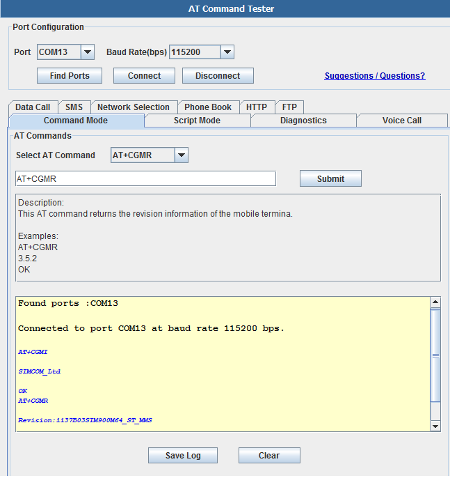
In the 'Port Configuration' section of the tool, users can search for available ports using the 'Find Ports' button. Then using the 'Connect' button, users can connect to the modem port of the device.
In the 'Command Mode' tab of AT Command Tester, single AT commands can be sent. The drop down list provides AT command description and examples. Users can modify the default command settings.
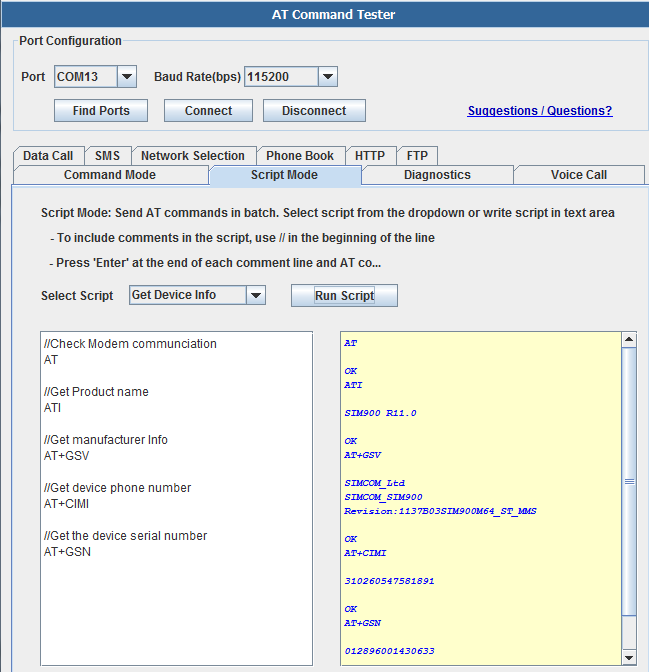
Under the 'Script Mode' tab, multiple AT commands can be sent at a time. Users can add descriptive comments and save the script on their local machine.
Data Call
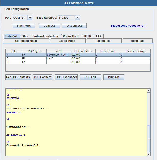
To make a data call with the modem, you need to connect to the APN of the carrier network. The carrier APN and other required information are stored in the SIM card and are referred as PDP contexts. Typically multiple PDP contexts are stored in the SIM for different call types. With the AT Command Tester you can edit/add/delete PDP contexts in a easy to use user interface.
Typical call setup sequence,
+CGDCONT: 1,"IP","epc.tmobile.com","0.0.0.0",0,0
+CGDCONT: 2,"IP","test5","0.0.0.0",0,0
+CGDCONT: 3,"IP","","0.0.0.0",0,0
OK
Checking registration status...
+CREG: 0,1
OK
The device is registered in home network.
Checking if device is already connected...
+CGACT: 1,0
+CGACT: 2,0
+CGACT: 3,0
OK
Attaching to network...
AT+CGATT=1
OK
Connecting...
OK
Connect Sucessful
SMS
The SMS tab of the 'AT Command Tester' tool provides the interfaces to send SMS messages. You can also list/view/delete SMS messages stored on the SIM.
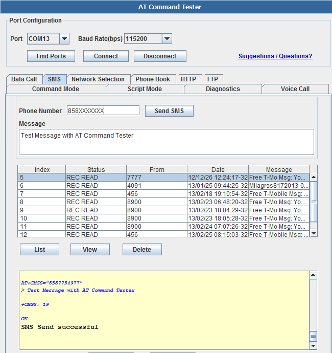
General sequence for sending SMS message,
Checking registration status...
+CREG: 0,1
OK
The device is registered in home network.
AT+CMGS="858XXXXXXX"
> Test Message with AT Command Tester�
+CMGS: 19
OK
SMS Send successful
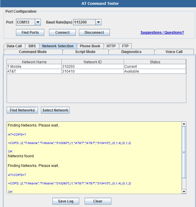
Network Selection - This tab allows the user to manually select available networks. Modems are typically set for automatic network selection. 'Find Networks' button will command the modem to scan for available networks.
AT+COPS command will initiate network scan in the modem,
Finding Networks. Please wait..
+COPS: (2,"T-Mobile","T-Mobile","310260"),(1,"AT&T","AT&T","310410"),,(0,1,4),(0,1,2)
OK
Networks found
Phonebook
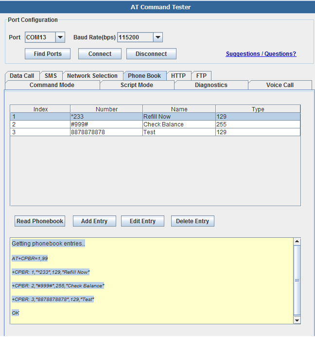
With the 'Phone Book' tab, you can add/delete/read phone book entries stored on the SIM,
Getting phonebook entries..
+CPBR: 1,"*233",129,"Refill Now"
+CPBR: 2,"#999#",255,"Check Balance"
+CPBR: 3,"8878878878",129,"Test"
OK
Example Project
Send SMS
For this project, the following is the jumper setting:
- TX-> MRX
- RX->MTX
- Please remove the USB cable after downloading the program
<syntaxhighlight lang="c">
char str1[]={'A','T','+','C','S','C','S','=','"','G','S','M','"'}; char str2[]={'A','T','+','C','M','G','S','=','"','1','5','9','7','2','1','6','9','1','8','9','"'}; int i; char inByte = 0; //unsigned char receive_ACK[6]; char hex1[]={0x1A}; void setup() {
 // start serial port at 9600 bps and wait for port to open:
 Serial.begin(9600);
 //while (!Serial) {
   ; // wait for serial port to connect. Needed for Leonardo only
// }
delay(8000); Serial.println(); for(i=10;i>0;i--) {delay(500); Serial.println("AT");}
delay(1000); Serial.println("AT"); delay(1000); for(i=0;i<13;i++) Serial.print(str1[i]); Serial.println(); delay(1000); Serial.println("AT+CMGF=1"); delay(1000); for(i=0;i<21;i++) Serial.print(str2[i]);//AT+CMGS="15972169189" Serial.println(); delay(1000); Serial.print("HELLO Sir,Thank you very much fit my test!"); delay(1000); Serial.print(hex1); delay(1000);
}
void loop() { /*
 Serial.println("AT");   delay(500);
if (Serial.available() > 0) {
   // get incoming byte:
   inByte = Serial.read();
   Serial.println(inByte);
}
*/
}
</syntaxhighlight>
Detect an event and send SMS to a cell phone number stored in SD card, and display alarm in 8X8 LED matrix
<syntaxhighlight lang="c">
- include <SD.h>
char str1[]={'A','T','+','C','S','C','S','=','"','G','S','M','"'}; //char str2[]={'A','T','+','C','M','G','S','=','"','1','5','9','7','2','1','6','9','1','8','9','"'}; char hex[]={0x1A}; char WORD;
char inByte = 0; File myFile; char RxBuffer[100];//ZHONGZHUAN char From[100];//1 char To[100];//2 char RxCounter = 0; char Enter=0; char From_len=0; char To_len=0;
const int analogInPin = A0; // Analog input pin that the potentiometer is attached to int sensorValue = 0; // value read from the pot int outputValue = 0; int count = 0; int count1 = 0;
unsigned char i; unsigned char j; unsigned char k; /*port definition*/ int Max7219_pinCLK = 10; int Max7219_pinCS = 9; int Max7219_pinDIN = 8; unsigned char data[2][6]={ {10,21,14,27,29}, {23,24,27,22,10,21},}; unsigned char disp1[39][8]={ {0x3C,0x42,0x42,0x42,0x42,0x42,0x42,0x3C},//0 {0x10,0x18,0x14,0x10,0x10,0x10,0x10,0x10},//1 {0x7E,0x2,0x2,0x7E,0x40,0x40,0x40,0x7E},//2 {0x3E,0x2,0x2,0x3E,0x2,0x2,0x3E,0x0},//3 {0x8,0x18,0x28,0x48,0xFE,0x8,0x8,0x8},//4 {0x3C,0x20,0x20,0x3C,0x4,0x4,0x3C,0x0},//5 {0x3C,0x20,0x20,0x3C,0x24,0x24,0x3C,0x0},//6 {0x3E,0x22,0x4,0x8,0x8,0x8,0x8,0x8},//7 {0x0,0x3E,0x22,0x22,0x3E,0x22,0x22,0x3E},//8 {0x3E,0x22,0x22,0x3E,0x2,0x2,0x2,0x3E},//9 {0x8,0x14,0x22,0x3E,0x22,0x22,0x22,0x22},//A {0x3C,0x22,0x22,0x3E,0x22,0x22,0x3C,0x0},//B {0x3C,0x40,0x40,0x40,0x40,0x40,0x3C,0x0},//C {0x7C,0x42,0x42,0x42,0x42,0x42,0x7C,0x0},//D {0x7C,0x40,0x40,0x7C,0x40,0x40,0x40,0x7C},//E {0x7C,0x40,0x40,0x7C,0x40,0x40,0x40,0x40},//F {0x3C,0x40,0x40,0x40,0x40,0x44,0x44,0x3C},//G {0x44,0x44,0x44,0x7C,0x44,0x44,0x44,0x44},//H {0x7C,0x10,0x10,0x10,0x10,0x10,0x10,0x7C},//I {0x3C,0x8,0x8,0x8,0x8,0x8,0x48,0x30},//J {0x0,0x24,0x28,0x30,0x20,0x30,0x28,0x24},//K {0x40,0x40,0x40,0x40,0x40,0x40,0x40,0x7C},//L {0x81,0xC3,0xA5,0x99,0x81,0x81,0x81,0x81},//M {0x0,0x42,0x62,0x52,0x4A,0x46,0x42,0x0},//N {0x3C,0x42,0x42,0x42,0x42,0x42,0x42,0x3C},//O {0x3C,0x22,0x22,0x22,0x3C,0x20,0x20,0x20},//P {0x1C,0x22,0x22,0x22,0x22,0x26,0x22,0x1D},//Q {0x3C,0x22,0x22,0x22,0x3C,0x24,0x22,0x21},//R {0x0,0x1E,0x20,0x20,0x3E,0x2,0x2,0x3C},//S {0x0,0x3E,0x8,0x8,0x8,0x8,0x8,0x8},//T {0x42,0x42,0x42,0x42,0x42,0x42,0x22,0x1C},//U {0x42,0x42,0x42,0x42,0x42,0x42,0x24,0x18},//V {0x0,0x49,0x49,0x49,0x49,0x2A,0x1C,0x0},//W {0x0,0x41,0x22,0x14,0x8,0x14,0x22,0x41},//X {0x41,0x22,0x14,0x8,0x8,0x8,0x8,0x8},//Y {0x0,0x7F,0x2,0x4,0x8,0x10,0x20,0x7F},//Z {0x8,0x7F,0x49,0x49,0x7F,0x8,0x8,0x8},//Chinese Character 中 {0xFE,0xBA,0x92,0xBA,0x92,0x9A,0xBA,0xFE},//Chinese Character国 {0xFF,0xFF,0xFF,0xFF,0xFF,0xFF,0xFF,0xFF}, };
void Write_Max7219_byte(unsigned char DATA)
{
unsigned char i;
digitalWrite(Max7219_pinCS,LOW); for(i=8;i>=1;i--)
         {
            digitalWrite(Max7219_pinCLK,LOW);
            digitalWrite(Max7219_pinDIN,DATA&0x80);
            DATA = DATA<<1;
            digitalWrite(Max7219_pinCLK,HIGH);
          }
}
void Write_Max7219(unsigned char address,unsigned char dat)
{
       digitalWrite(Max7219_pinCS,LOW);
       Write_Max7219_byte(address);
       Write_Max7219_byte(dat);
       digitalWrite(Max7219_pinCS,HIGH);
}
void Init_MAX7219(void) {
Write_Max7219(0x09, 0x00);
Write_Max7219(0x0a, 0x03);
Write_Max7219(0x0b, 0x07);
Write_Max7219(0x0c, 0x01);
Write_Max7219(0x0f, 0x00);
}
void Alert(void) {
 for(i=1;i<9;i++)
   Write_Max7219(i,disp1[10][i-1]);
  delay(500);
  for(i=1;i<9;i++)
   Write_Max7219(i,disp1[21][i-1]);
  delay(500);
  for(i=1;i<9;i++)
   Write_Max7219(i,disp1[14][i-1]);
  delay(500);
  for(i=1;i<9;i++)
   Write_Max7219(i,disp1[27][i-1]);
  delay(500);
  for(i=1;i<9;i++)
   Write_Max7219(i,disp1[29][i-1]);
  delay(1500);
} void Normal(void) {
  for(i=1;i<9;i++)
   Write_Max7219(i,disp1[23][i-1]);
  delay(500);
  for(i=1;i<9;i++)
   Write_Max7219(i,disp1[24][i-1]);
  delay(500);
  for(i=1;i<9;i++)
   Write_Max7219(i,disp1[27][i-1]);
  delay(500);
  for(i=1;i<9;i++)
   Write_Max7219(i,disp1[22][i-1]);
  delay(500);
  for(i=1;i<9;i++)
   Write_Max7219(i,disp1[10][i-1]);
  delay(500);
  for(i=1;i<9;i++)
   Write_Max7219(i,disp1[21][i-1]);
  delay(1500);
}
void Message(void) { delay(1000); Serial.println(); for(i=2;i>0;i--) {delay(500); Serial.println("AT");} delay(1000); Serial.println("AT"); delay(1000); for(i=0;i<13;i++) Serial.print(str1[i]); Serial.println(); delay(1000); Serial.println("AT+CMGF=1"); delay(1000); for(char i=0;i<From_len;i++) Serial.print(From[i]);//AT+CMGS="15972169189" Serial.println(); delay(1000); for(char i=0;i<To_len;i++) Serial.print(To[i]); delay(1000); Serial.print(hex); delay(1000); }
void SDHC(void) { Serial.println("Initializing SD card...");
 // On the Ethernet Shield, CS is pin 4. It's set as an output by default.
 // Note that even if it's not used as the CS pin, the hardware SS pin
 // (10 on most Arduino boards, 53 on the Mega) must be left as an output
 // or the SD library functions will not work.
  pinMode(10, OUTPUT);

 if (!SD.begin(4)) {
   Serial.println("initialization failed!");
   return;
 }
 Serial.println("initialization done.");

 // re-open the file for reading:
 myFile = SD.open("test.txt");
 if (myFile) {
   Serial.println("test.txt:");

   // read from the file until there's nothing else in it:
   while (myFile.available()) {
       char i;
       RxBuffer[RxCounter++] = myFile.read();
       if(RxBuffer[RxCounter-2]==0x0d&&RxBuffer[RxCounter-1]==0x0a)//0x0d huiche \ ,0x0a huanhang \n
{ Enter++; switch(Enter) { case 1: for(i=0; i< RxCounter-2; i++) From[i]= RxBuffer[i];
From_len=RxCounter-2;
;break; case 2: for(i=0; i< RxCounter-2; i++) To[i]= RxBuffer[i];
To_len=RxCounter-2;
;break; default:;break; }
RxCounter=0; }
   }
   // close the file:
   myFile.close();
 } else {
 	// if the file didn't open, print an error:
   Serial.println("error opening test.txt");
 }

 for(char i=0;i<From_len;i++)
   	Serial.write( To[i]);
       Serial.println();

 for(char i=0;i<To_len;i++)
   	Serial.write( From[i]);
       Serial.println();
}
void setup() {
 Serial.begin(9600);

 pinMode(Max7219_pinCLK,OUTPUT);
 pinMode(Max7219_pinCS,OUTPUT);
 pinMode(Max7219_pinDIN,OUTPUT);
 delay(50);
 Init_MAX7219();
 SDHC();
}
void loop()
{
// if(count<50)
 //{
// count++;

 //Normal();
 sensorValue = analogRead(analogInPin);
 outputValue = map(sensorValue, 0, 1023, 0, 255);
 Serial.print("sensor = ");
 Serial.print(sensorValue);
 Serial.print("\t output = ");
 Serial.println(outputValue);
 delay(500);
 if(outputValue>=60)
    {
     // count=0;
      //Alert();
      if(count1<3)
      Message();
      count1++;
    }
// }
// else if(count=10)
// {
 //Message();
 //}
}
</syntaxhighlight>
FAQ
Please list your question here:
Support
If you have questions or other better design ideas, you can go to our forum to discuss or creat a ticket for your issue at linksprite support.
Resources
- AT Command Tester Tool
- Send single or batch AT commands
- Perform modem diagnostics
- Set up GSM/GPRS call
- Send single or batch AT commands
How to buy
Here to buy ATWIN Quad-band GPRS/GSM Shield for Arduino on store
See Also
Other related products and resources.
Licensing
This documentation is licensed under the Creative Commons Attribution-ShareAlike License 3.0 Source code and libraries are licensed under GPL/LGPL, see source code files for details.
