Difference between revisions of "Touch Shield for Arduino"
| (2 intermediate revisions by the same user not shown) | |||
| Line 6: | Line 6: | ||
[[File:N93DG WITHOUT PACKAGED BACK.jpg|640px]] | [[File:N93DG WITHOUT PACKAGED BACK.jpg|640px]] | ||
| + | |||
| + | Below photos are for shield without headers: | ||
| + | |||
| + | |||
| + | [[File:Touch Shield for Arduino 001.jpg|640px]] | ||
| + | |||
| + | [[File:Touch Shield for Arduino 002.jpg|640px]] | ||
| + | |||
| + | [[File:Touch Shield for Arduino 003.jpg|640px]] | ||
Latest revision as of 12:43, 20 June 2016
Contents
Introduction
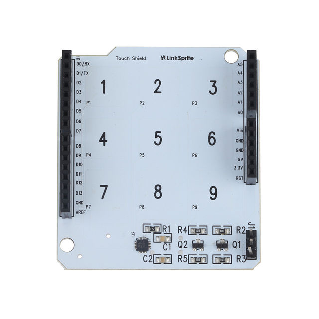
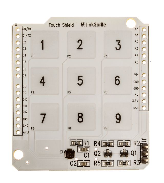
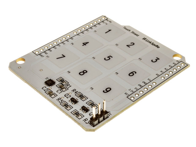
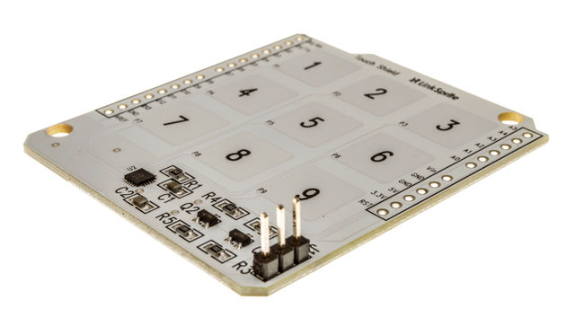
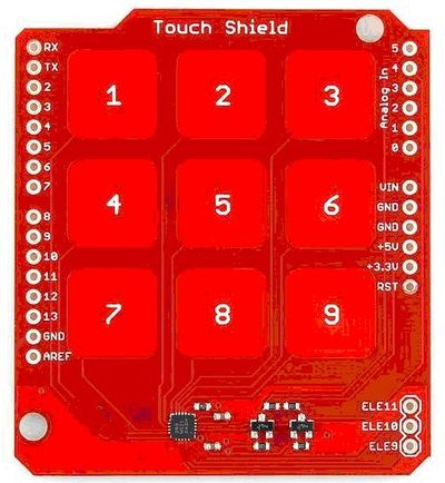
The MPR121 IC is a great way to build simple capacitive touch interfaces, and now it's even easier to incorporate into your Arduino projects with the touch shield. The touch shield has 9 capacitive touch pads, with headers for the remaining 3 electrode connections. With this shield you can have a total of 12 touch sensitive buttons. An on-board logic level converter allows it to work with 5V and 3.3V Arduino boards. Simply solder on some header pins and stack it on to your Arduino for a convenient input device. Check below for some example code to get you started.
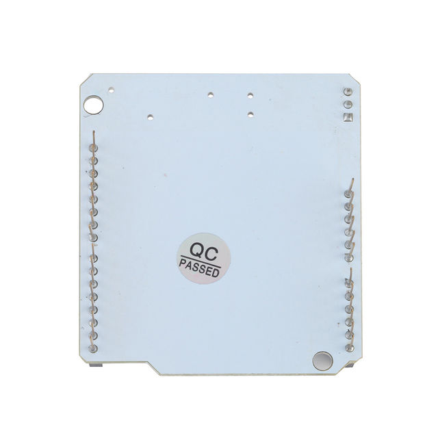
Below photos are for shield without headers:
Features
Application Ideas
Cautions
Schematic
Specification
Pin definition and Rating
Mechanic Dimensions
Usage
Test Report
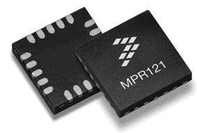
This board use the MPR121 as the main IC,This IC can connect 12 pads,8 of the 12 pads can be usd as the second functions(driving the leds),The supply voltage vary from 1.71v to 3.6v. The circuit can be as low as 29uA at the sampling rate of 16ms,The IC communicatie with the MCU Through interrupt or I2C.
We used 9 pads on our board as input,This board can be placed on the arduino board conveniently.
Programming
instructions
This board use the 3.3v voltage of the arduino board,it communicate with the arduino board through I2C,the voltage of the MCU’s IO is 5V, in order to compatible with the Tocuth shield board voltage , the board used 2 MOS FET to solve the problems.
- SDA------A4
- SCK------A5
- interrupt------D2
test procedure
software platform: arduino
test code:see the attachment
code procedure:
init the I2C
init MPR121
enable the interrupt
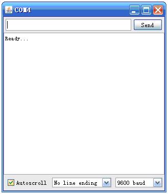
handle the interrupt process,send the data through UART
notice: The interrupt handle function cannot work with the condition more than two key push down at the same time.
after the initialize
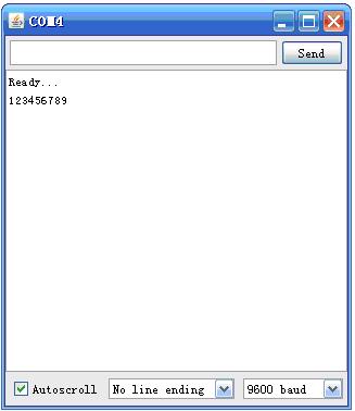
The interrupt function send the data to the PC when the key is pressed
FAQ
Please list your question here:
Support
If you have questions or other better design ideas, you can go to our forum to discuss or creat a ticket for your issue at linksprite support.
Resources
How to buy
Here to buy Touch Shield for Arduino on store
See Also
Other related products and resources.
Licensing
This documentation is licensed under the Creative Commons Attribution-ShareAlike License 3.0 Source code and libraries are licensed under GPL/LGPL, see source code files for details.
