Difference between revisions of "SD Card Breakout Board"
Katherine.d (talk | contribs) (→Resource) |
(→Description) |
||
| (2 intermediate revisions by 2 users not shown) | |||
| Line 12: | Line 12: | ||
#*'''pin 10''' (PB2): SS- (slave select, active low); goes to "pin 1" of the SD-card (its chip-select); | #*'''pin 10''' (PB2): SS- (slave select, active low); goes to "pin 1" of the SD-card (its chip-select); | ||
| − | [[File: | + | [model:[http://www.linkspritedirect.com/product_info.php?products_id=149 BB_SD]] |
| + | |||
| + | |||
| + | |||
| + | [[File:SD Card Breakout 105101003-1.jpg|640 px]] | ||
| + | |||
| + | [[File:SD Card Breakout 105101003-2.jpg|640 px]] | ||
| + | |||
| + | [[File:SD Card Breakout 105101003-3.jpg|640 px]] | ||
== Resource == | == Resource == | ||
*[https://s3.amazonaws.com/linksprite/breakout/SD_card_breakout/1284178585.rar Arduino SD files including library from LinkSprite] | *[https://s3.amazonaws.com/linksprite/breakout/SD_card_breakout/1284178585.rar Arduino SD files including library from LinkSprite] | ||
*[http://www.alfonsomartone.itb.it/kfmdxc.html Reference] | *[http://www.alfonsomartone.itb.it/kfmdxc.html Reference] | ||
Latest revision as of 06:33, 30 June 2016
Description
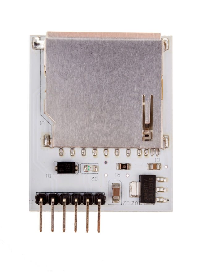
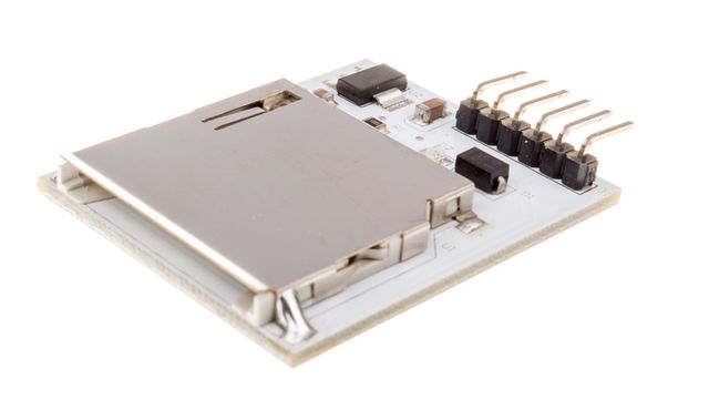
This board does the 3.3V to 5V translation. So you can direcly plug it to Arduino. The Vcc of this board is 5V!
Why? Arduino has 512 bytes EEPROM (which does not loose its contents at power off) and 1024 bytes RAM (which contents are lost at power off). To get more storage, a SD-card solution (MMC, secure-digital, micro-SD, etc) is the cheapest way to have a few gigabytes of storage for data logging.
Using a secure-digital (SD) card with the Arduino is quite easy, as long as we use its "slow" mode (via SPI and without interrupts) and only read/write single sectors (no "burst" modes).
Hardware: we only need four pins (3 out, 1 in):
- pin 13 (PB5): SCK (slave clock input, master clock output: sadly this Arduino pin has a SMD LED which now we cannot use anymore for software debugging); goes to "pin 5" of the SD-card;
- pin 12 (PB4): MISO (master in, slave out: the only "input" pin of these four); goes to "pin 7" of the SD-card (its data output);
- pin 11 (PB3): MOSI (master out, slave in); goes to "pin 2" of the SD-card (its data input);
- pin 10 (PB2): SS- (slave select, active low); goes to "pin 1" of the SD-card (its chip-select);
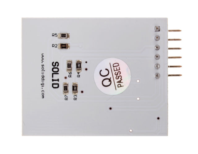
[model:BB_SD]


