Difference between revisions of "MQ2 Smoke Detector Shield for Arduino"
Katherine.d (talk | contribs) (→Introduction) |
(→Resources) |
||
| (6 intermediate revisions by 3 users not shown) | |||
| Line 8: | Line 8: | ||
Connecting five volts across the heating (H) pins keeps the sensor hot enough to function correctly. Connecting five volts at either the A or B pins causes the sensor to emit an analog voltage on the other pins. A resistive load between the output pins and ground sets the sensitivity of the detector. Please note that the picture in the datasheet for the top configuration is wrong. Both configurations have the same pinout consistent with the bottom configuration.The resistive load should be calibrated for your particular application using the equations in the datasheet, but a good starting value for the resistor is 20 kΩ. | Connecting five volts across the heating (H) pins keeps the sensor hot enough to function correctly. Connecting five volts at either the A or B pins causes the sensor to emit an analog voltage on the other pins. A resistive load between the output pins and ground sets the sensitivity of the detector. Please note that the picture in the datasheet for the top configuration is wrong. Both configurations have the same pinout consistent with the bottom configuration.The resistive load should be calibrated for your particular application using the equations in the datasheet, but a good starting value for the resistor is 20 kΩ. | ||
| − | [[File: | + | [[File:N98DG WITHOUT PACKAGED FRONT.jpg | 640px]] |
| + | |||
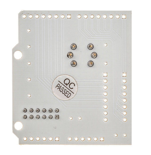
| + | [[File:N98DG WITHOUT PACKAGED BACK.jpg|640px]] | ||
| + | |||
| + | Below photos are for shields without headers: | ||
| + | |||
| + | [[File:MQ2 Smoke Detector Shield for Arduino 001.jpg|640px]] | ||
| + | |||
| + | [[File:MQ2 Smoke Detector Shield for Arduino 002.jpg|640px]] | ||
| + | |||
| + | [[File:MQ2 Smoke Detector Shield for Arduino 003.jpg|640px]] | ||
== Features == | == Features == | ||
| Line 143: | Line 153: | ||
*[https://s3.amazonaws.com/linksprite/Shields/MQ2/MQ2.pdf MQ2 Datasheet] | *[https://s3.amazonaws.com/linksprite/Shields/MQ2/MQ2.pdf MQ2 Datasheet] | ||
| + | *[https://s3.amazonaws.com/linksprite/MQ-2/TECHNICAL+DATA+MQ-2+GAS+SENSOR.pdf TECHNICAL DATA MQ-2 GAS SENSOR] | ||
== How to buy == | == How to buy == | ||
| − | You can order from [http:// | + | You can order from [http://store.linksprite.com/mq2-smoke-detector-shield-for-arduino-pcduino/ LinkSprite Store] or [http://www.cutedigi.com/arduino-shields/mq2-smoke-detector-shield-for-arduino.html CuteDigi]. |
== See Also == | == See Also == | ||
Latest revision as of 04:36, 3 July 2016
Contents
Introduction
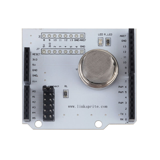
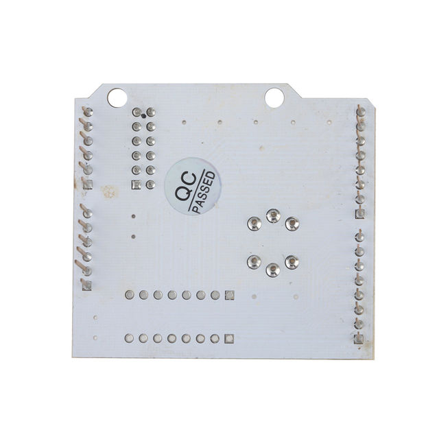
MQ2 flammable gas and smoke sensor detects the concentrations of combustible gas in the air and ouputs its reading as an analog voltage. The sensor can measure concentrations of flammable gas of 300 to 10,000 ppm.The sensor can operate at temperatures from -20 to 50°C and consumes less than 150 mA at 5 V.
Connecting five volts across the heating (H) pins keeps the sensor hot enough to function correctly. Connecting five volts at either the A or B pins causes the sensor to emit an analog voltage on the other pins. A resistive load between the output pins and ground sets the sensitivity of the detector. Please note that the picture in the datasheet for the top configuration is wrong. Both configurations have the same pinout consistent with the bottom configuration.The resistive load should be calibrated for your particular application using the equations in the datasheet, but a good starting value for the resistor is 20 kΩ.
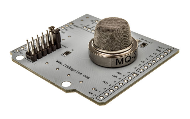
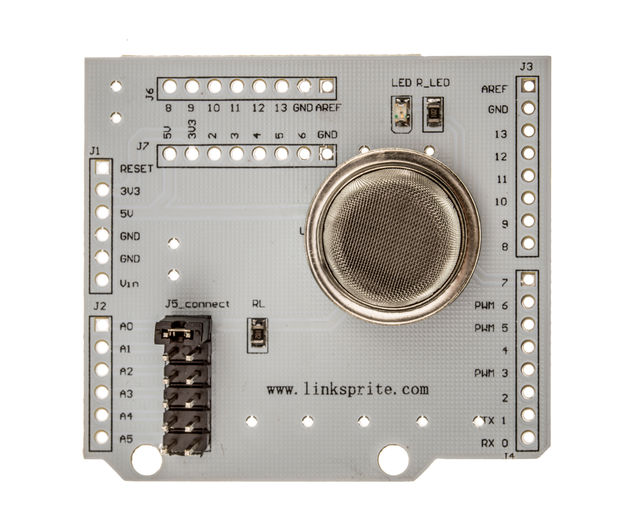
Below photos are for shields without headers:
Features
Application Ideas
Cautions
Schematic
Specification
Pin definition and Rating
Mechanic Dimensions
Usage
Hardware Installation
Programming
Sample Program
<syntaxhighlight lang="c">
/* Sample Arduino for MQ2 Smoke Sensor Shield
05/03/2011
- /
const int analogInPin = A0; // Analog input pin that the potentiometer is attached to const int analogOutPin = 9; // Analog output pin that the LED is attached to
int sensorValue = 0; // value read from the pot int outputValue = 0; // value output to the PWM (analog out) float thickness; int count,count1;
void setup() {
 // initialize serial communications at 9600 bps:
 Serial.begin(9600);
 pinMode(7, OUTPUT);
}
void loop() {
 count1++;
 // read the analog in value:
 sensorValue = analogRead(analogInPin);
 // map it to the range of the analog out:
 outputValue = map(sensorValue, 0, 1023, 0, 255);
 // change the analog out value:
 analogWrite(analogOutPin, outputValue);
 if(count1==30)
 {
   count1=0;
   // print the results to the serial monitor:
   Serial.print("sensor = " );
   Serial.print(sensorValue);
   Serial.print("\t output = ");
   Serial.println(outputValue);

   thickness = 20000-(5000*(1023/(float)sensorValue)-1);         //This relationship is wrong,According to demand, own calculations relationship
   Serial.print("thicknes = ");
   Serial.println( thickness);
 }
 count++;
 if(count>=(255-outputValue))
 {
   count=0;
 }
 if(count < (255-outputValue)/2)
 {
   digitalWrite(7, HIGH);   // set the LED on
   delay(20);
 }
// delay(1023-sensorValue);
 else
 {
   digitalWrite(7, LOW);    // set the LED off
   delay(20);
 }
// delay(1023-sensorValue);
}
</syntaxhighlight>
FAQ
Please list your question here:
Support
If you have questions or other better design ideas, you can go to our forum to discuss or creat a ticket for your issue at linksprite support.
Resources
How to buy
You can order from LinkSprite Store or CuteDigi.
See Also
Other related products and resources.
Licensing
This documentation is licensed under the Creative Commons Attribution-ShareAlike License 3.0 Source code and libraries are licensed under GPL/LGPL, see source code files for details.
