Difference between revisions of "LDR Module"
(→Introduction) |
|||
| (18 intermediate revisions by 3 users not shown) | |||
| Line 1: | Line 1: | ||
| − | + | ==Introduction== | |
| + | |||
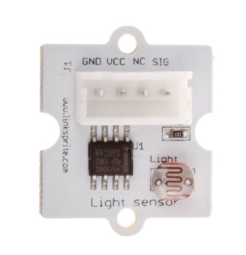
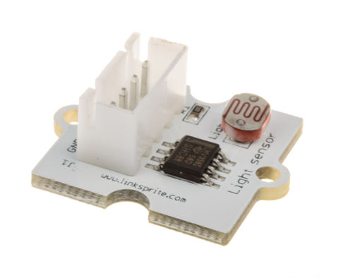
| + | The light sensor, also known as the light dependent resistor (LDR). Typically, the resistance of the light sensor will decrease when the ambient light intensity increases. | ||
| + | |||
| + | |||
| + | |||
| + | [[File:LDR Module 118101003 first.jpg| 500px]] | ||
| + | |||
| + | [[File:LDR Module 118101003 second.jpg| 500px]] | ||
| + | [[File:LDR Module 118101003 third.jpg| 500px]] | ||
| − | + | == Features == | |
| − | |||
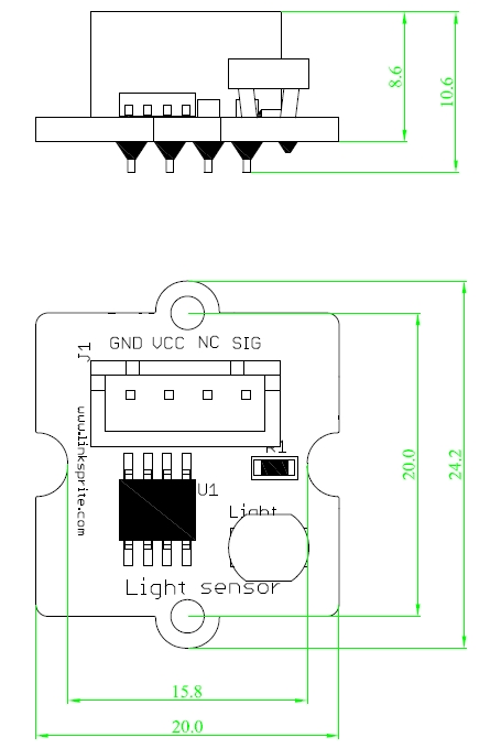
| − | + | Dimensions: 20.0×24.2×10.6mm | |
| − | |||
| − | |||
| − | + | Net weight: 1.9g | |
| − | |||
| − | |||
| − | |||
| − | |||
| − | + | == Dimension == | |
| − | + | [[File:light sensor dimension.jpg]] | |
| − | + | ==Schematics== | |
| − | |||
| − | |||
| − | |||
| − | |||
| − | |||
| − | |||
| − | |||
| − | |||
| − | |||
| − | |||
| − | |||
| − | // | + | *[https://s3.amazonaws.com/linksprite/LinkerKit/Light+sensor.pdf Schematics] |
| − | // | ||
| − | |||
| − | |||
| − | + | ==Application Ideas== | |
| − | |||
| + | ''' test code ''' | ||
| + | <syntaxhighlight lang="c"> | ||
| + | #include <math.h> | ||
| + | const int ledPin=12; //Connect the Linker LED module to Pin12, Digital 12 | ||
| + | const int thresholdvalue=10; //The treshold for which the LED should turn on. Setting it lower will make it go on at more light, higher for more darkness | ||
| + | |||
void setup() { | void setup() { | ||
| − | // | + | Serial.begin(9600); //Start the Serial connection |
| − | + | pinMode(ledPin,OUTPUT); //Set the LED on Digital 12 as an OUTPUT | |
} | } | ||
| − | |||
void loop() { | void loop() { | ||
| − | + | int sensorValue = analogRead(0); //Connect the Linker LDR module to A0, Analog 0 | |
| − | + | float Rsensor; | |
| − | + | Rsensor=(float)(1023-sensorValue)*10/sensorValue; | |
| − | + | ||
| − | + | if(Rsensor>thresholdvalue) | |
| − | + | { | |
| − | + | digitalWrite(ledPin,HIGH); | |
| − | + | } | |
| − | + | else | |
| − | + | { | |
| − | + | digitalWrite(ledPin,LOW); | |
| − | Serial.println( | + | } |
| + | |||
| + | Serial.println(Rsensor,DEC); | ||
| + | } | ||
| + | </syntaxhighlight> | ||
| − | + | [[File:LDR link.jpg]] | |
| − | |||
| − | |||
| − | |||
| − | |||
| − | + | ==How to buy== | |
| + | Here to buy LRD Module on [http://store.linksprite.com/ldr-ambient-light-module-of-linker-kit-for-pcduino-arduino/ store] | ||
Latest revision as of 10:34, 18 July 2016
Introduction
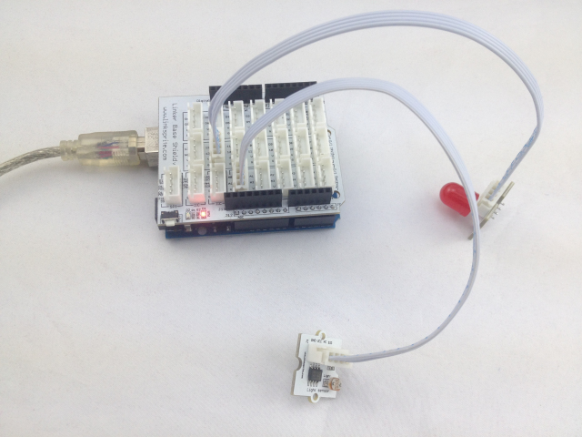
The light sensor, also known as the light dependent resistor (LDR). Typically, the resistance of the light sensor will decrease when the ambient light intensity increases.
Features
Dimensions: 20.0×24.2×10.6mm
Net weight: 1.9g
Dimension
Schematics
Application Ideas
test code <syntaxhighlight lang="c">
- include <math.h>
const int ledPin=12; //Connect the Linker LED module to Pin12, Digital 12 const int thresholdvalue=10; //The treshold for which the LED should turn on. Setting it lower will make it go on at more light, higher for more darkness
void setup() {
 Serial.begin(9600);                //Start the Serial connection
 pinMode(ledPin,OUTPUT);            //Set the LED on Digital 12 as an OUTPUT
} void loop() {
 int sensorValue = analogRead(0);  //Connect the Linker LDR module to A0, Analog 0
 float Rsensor;
 Rsensor=(float)(1023-sensorValue)*10/sensorValue;

 if(Rsensor>thresholdvalue)
 {
   digitalWrite(ledPin,HIGH);
 }
 else
 {
 digitalWrite(ledPin,LOW);
 }

 Serial.println(Rsensor,DEC);
} </syntaxhighlight>
How to buy
Here to buy LRD Module on store
