Difference between revisions of "PcDuino ASU VIPLE Robot V2.0"
(→Introduction to pcDuino Robot assembly) |
(→Introduction to pcDuino Robot assembly) |
||
| Line 115: | Line 115: | ||
Use the following pictures to check your wiring. | Use the following pictures to check your wiring. | ||
| − | [[File:方形viple小车 | + | [[File:方形viple小车 5.png|640px]] |
When the wiring is complete, launch the pcDuino Robot, wait for the indicator light of the Wi-Fi module lighting up. After a while the Robot will automatically create a Wi-Fi Hotspot named pcDuino-xxxx. | When the wiring is complete, launch the pcDuino Robot, wait for the indicator light of the Wi-Fi module lighting up. After a while the Robot will automatically create a Wi-Fi Hotspot named pcDuino-xxxx. | ||
Latest revision as of 03:12, 27 February 2017
Contents
Introduction
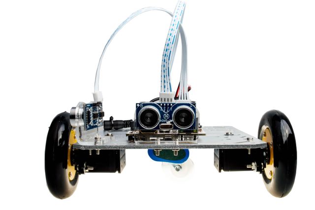
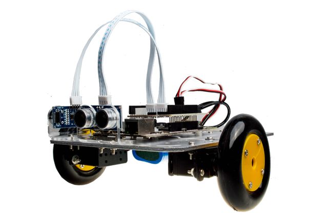
pcDuino Robot is a programmable Robot which supports ASU VIPLE graphical programming. We use ASU VIPLE tool to program. Then drive the robot forward, backward or turn it around by remotely controlling via Wi-Fi. And it is also easy to remotely access system via Wi-Fi hotspot, VNC or ssh tool. pcDuino Robot is powered by pcDuino3B and runs Ubuntu 12.04 OS. There are two ultrasonic sensors on the robot which are used to get relative distance from itself to the obstacles. Thus we can use different algorithm to control the robot, and let it find out way of a maze.
Hardware specifications
- pcDuino3B
- Allwinner A20 Dual-core ARM Cortex A7
- 1GB RAM
- 8G SD flash
- Onboard WiFi module
- Arduino-comptiable slot
- Power shield for driving pcDuino3B and servo motor
- Ultrasonic sensor HC-RS04 x 2
- High quality continuous rotation servo motor (5V DC)x 2
- 7.4V 18650 lithium battery
- 8.4V battery charger
- Aluminium robot platform
Software specifications
- OS on Robot
- Ubuntu 12.04
- Programming tool
- ASU VIPLE program supporting Win7 or later
Features
- Robot supporting ASU VIPLE graphical programming
- Wi-Fi control
- Maze algorithm implementation
Introduction to pcDuino Robot assembly
1.Chassis assembly
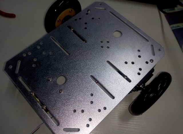
- Secure the two servo motors to the chassis with screws
- Secure the wheels to the servo motors with screws
- Secure the caster to the chassis with screws
Note:The caster and the two wheels should be at the same height,and you need to add shims if necessary.
Use the following pictures to check whether the installation is correct.
2.Pallet assembly
- Use three copper studs to attach the pcDuino3B to the pallet
- The Ultrasonic Sensor has been installed on the bracket, so you just need to secure the two ultrasonic brackets to the pallet
- Stick the label to a free position of the pallet
Note: The two ultrasonic sensors should be placed at the front and right respectively.
Check whether the installation is correct according to the following pictures.
3.Complete Robot assembly
- Use two screws to secure the chassis and the pallet together.
Note that the caster points to the front.
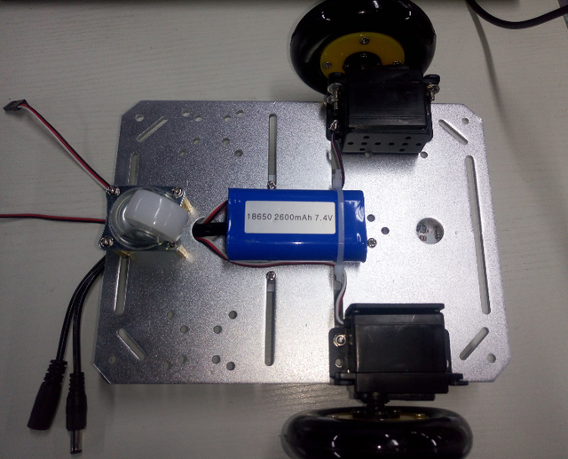
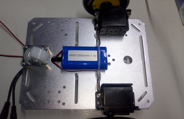
- Secure the battery to the caster side with a cable tie as the following picture
- Secure the charging port of the battery to the pallet with a cable tie
Wiring
- Connect the Power Base Shield to the pcDuino3B
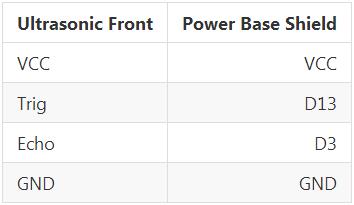
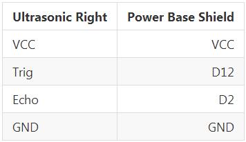
- Connect the ultrasonic sensor to the Power Base Shield according to the following tables
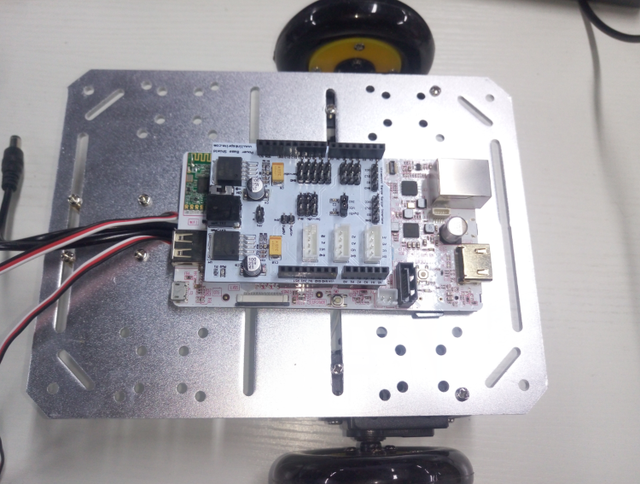
Use the following pictures to check your wiring.
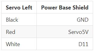
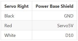
Connect the servo motors to the Power Base Shield according to the following tables
- Connect the battery power output to the Power Base Shield power input
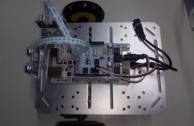
Use the following pictures to check your wiring.
When the wiring is complete, launch the pcDuino Robot, wait for the indicator light of the Wi-Fi module lighting up. After a while the Robot will automatically create a Wi-Fi Hotspot named pcDuino-xxxx.
If you want to watch the assembly video, click PcDuino Robot assembly video tutorial
Introduction to ASU VIPLE
1. Install ASU VIPLE tool
We need a Windows PC with a wireless network card, because we want PC and pcDuino Robot to communicate via Wi-Fi. The system version requires Win7 or later.
Click here and download ASU VIPLE tool, Unzip and run VIPLE.exe.
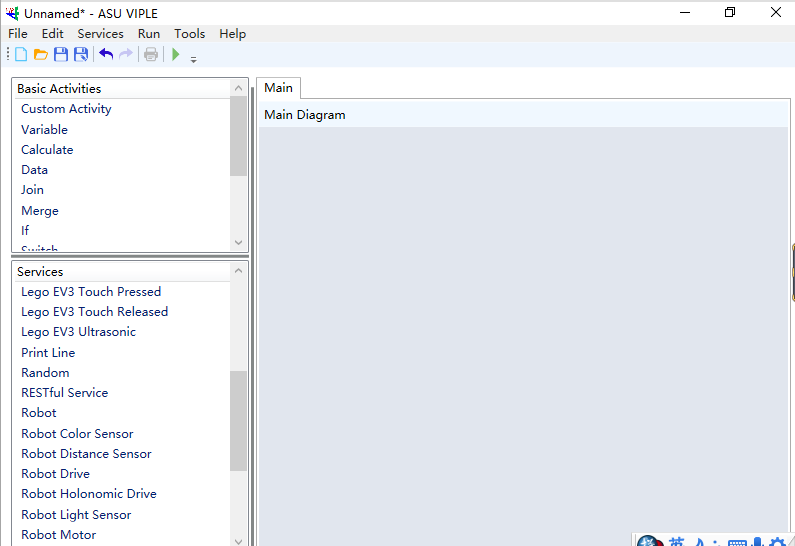
ASU VIPLE programming Languageis is similar to Microsoft VPL. As shown in the picture,the left sidebar provides a series of graphical programming components:
- Basic Activities can be used for constructing programs, including Data, Variables,If/Else, While, Join, and so on.
- Services provides a set of modules used to connect to generic robots, sensors, and motor services.
2. Quick start to access ASU VIPLE
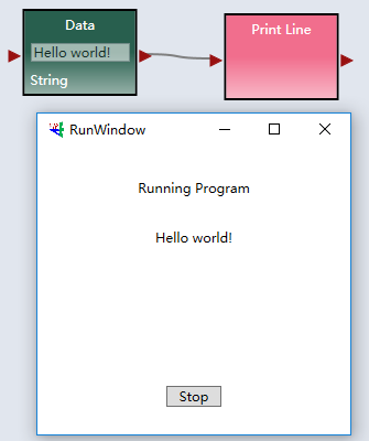
Hello World in ASU VIPLE
- Open the ASU VIPLE
- Create a new project. Press Ctrl + N or go to the toolbar and click File-->New
- Drag the Data module from the Basic Activities on the left
- Enter "Hello world!" into the Data module
- Drag the Print Line module from the Services on the left
- Connect these two modules
- Run it. Click the Run button in the toolbar or press F5
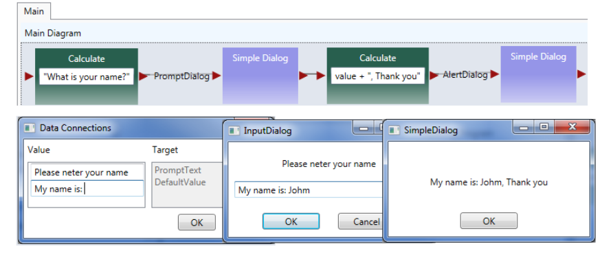
Input and Output in ASU VIPLE
- Create a new project
- Drag the Calculate module from the Basic Activities
- Drag the Simple Dialog module from the Services
- Connect and configure those modules according to the following figure
- Press F5 to run it
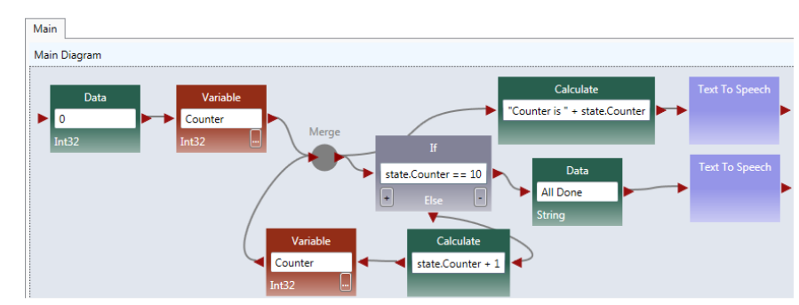
A Simple Counter in ASU VIPLE
- Connect and configure the modules according to the following figure
- Press F5 to run the program
For more ASU VIPLE programming information, please refer to [https://s3.amazonaws.com/linksprite/robot/viple/IntroductionVIPLE.pdf VIPLE Programming Guide].
Remote control Robots by ASU VIPLE
1. configuration of pcDuino Robot
The system will automatically create a Wi-Fi Hotspot when we launch the pcDuino Robots. And the basic information is as follows:
- Wi-Fi Hotspot: pcDuino-xxxx
- Password: 12345678
- IP address: 10.0.0.1
- Corresponding VIPLE service port number: 8124
Next, we will explain how VIPLE connects to pcDuino Robot.
- Launch the pcDuino Robot, wait for the indicator light of the Wi-Fi module lighting up
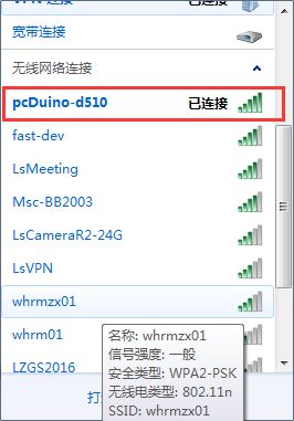
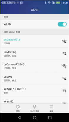
- Use your PC to connect this Wi-Fi Hotspot
- Open the network connection and search for the Wi-Fi Hotspot started with "pcDuino-"
- Choose it and enter the Wi-Fi password, wait for the connection to succeed
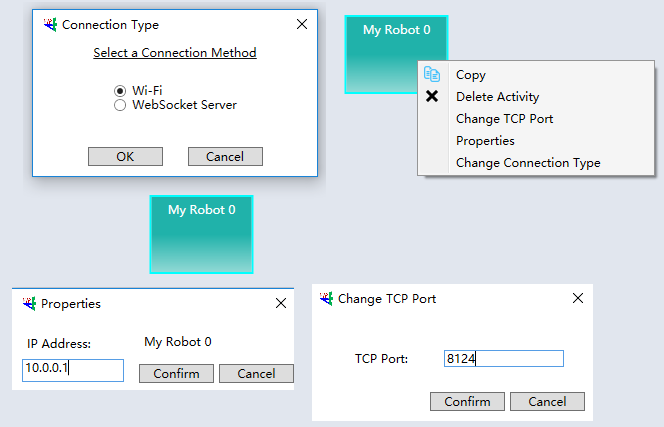
- Check and configure Robot module.
- Configure the basic communication information.
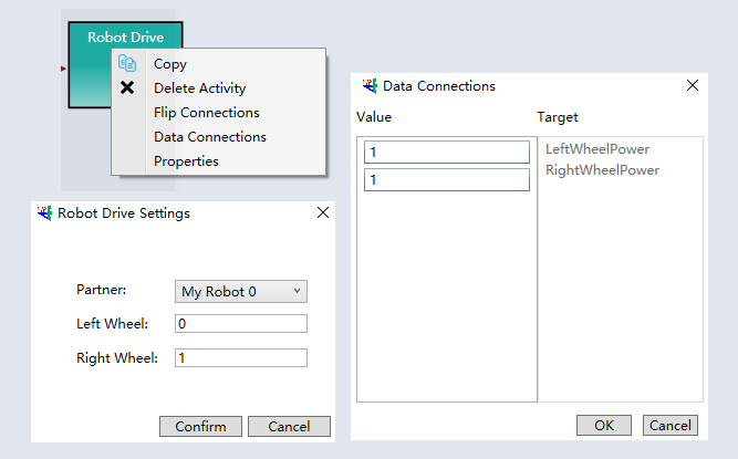
- Configure the servos.
- The two servos are numbered as 0 and 1 respectively.
- The range of speed is between -1.0 to 1.0.
- Check and configure Robot Distance Sensor Module
- Configure the ultrasonic sensor
- The two ultrasonic transducers are numbered as 0 and 1 respectively
Please refer to github to get specific test programs.
2. Test of pcDuino robot
Test of servos
- Open the ASU VIPLE
- Open the servo-control.xml project
- Make sure your PC has already connected to the Wi-Fi created by Robot
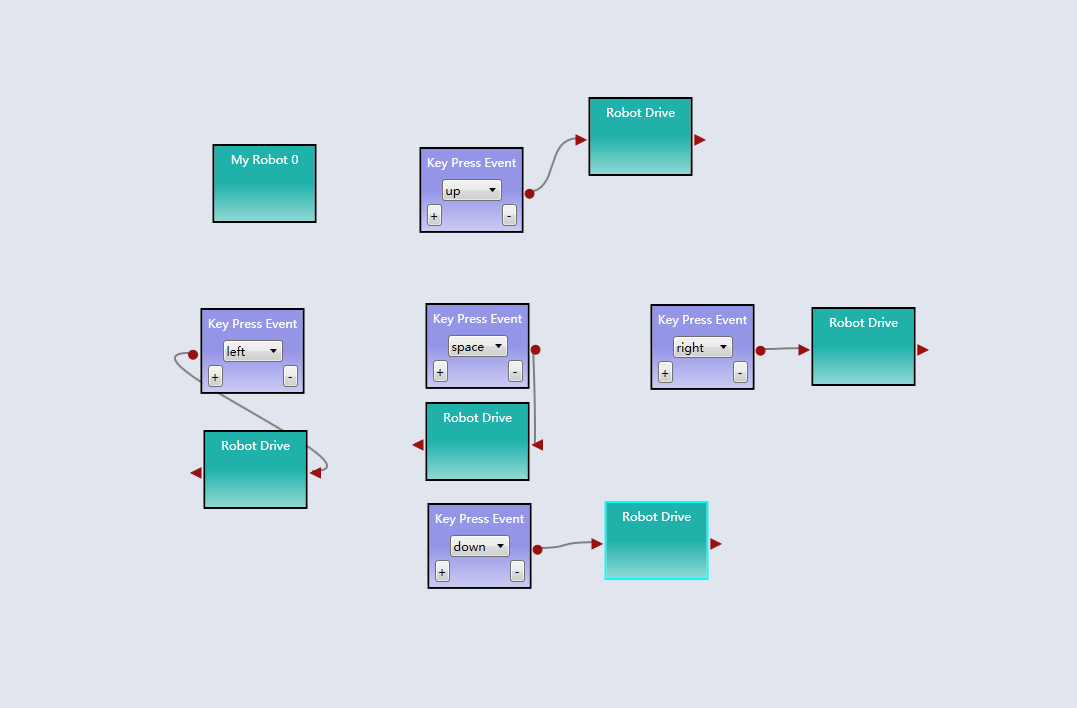
- Click the Run button in the toolbar, and press the arrow keys to control
The VIPLE code is as follows:
Test of Ultrasonic sensor
- Run ultrasonic.xml
- Observe the data displayed in the window
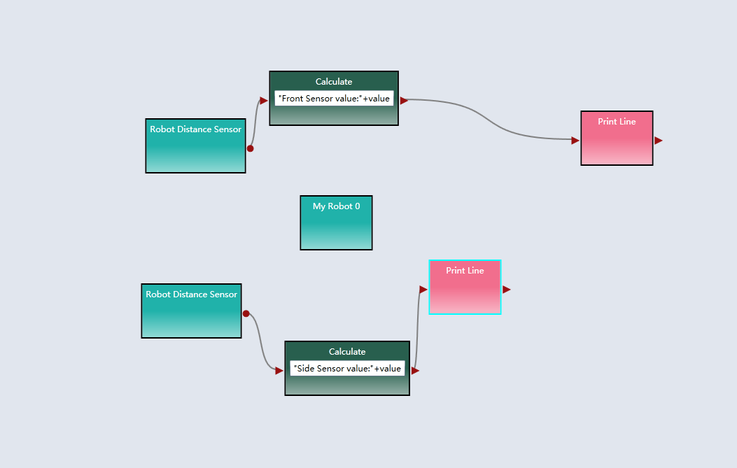
- Observe the changes of distance by manually adding obstacles
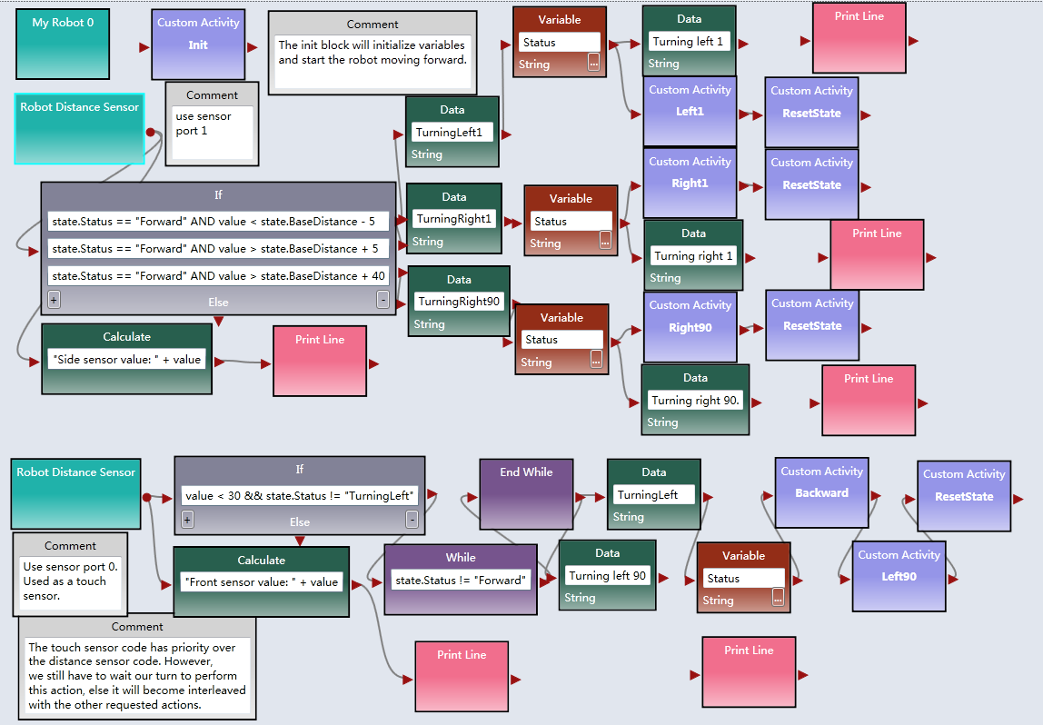
The VIPLE code is as follows:
- Run maze-resolve.xml
- Observe the pcDuino Robot's moving in a maze, and modify the corresponding parameters
Note: This project uses the right-wall-following algorithm.
The VIPLE code is as follows:
Remote control Robot by Android APP
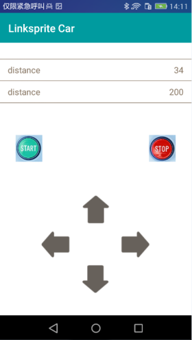
We have specifically developed a simple APP to test the basic functions of the Robot.
- Download and install App
- Launch the Robot. After a while the Robot will automatically create a Wi-Fi Hotspot named pcDuino-xxxx.
- Use your mobile phone to connect this Wi-Fi Hotspot
- Read the ultrasonic sensor data and control the moving of the Robot via the APP
