Difference between revisions of "MIDI Shield for Arduino"
(→Resources) |
|||
| (5 intermediate revisions by 2 users not shown) | |||
| Line 3: | Line 3: | ||
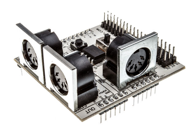
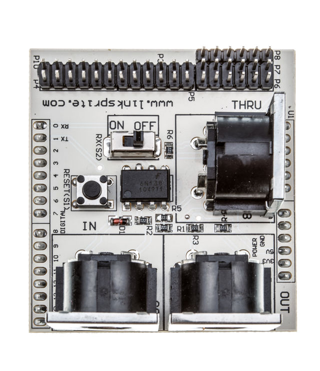
The MIDI Breakout board gives your Arduino or any other microcontroller access to the powerful MIDI communication protocol. The MIDI protocol shares many similarities with standard asynchronous serial interfaces, so you can use the UART pins of your microcontroller to send and receive MIDI's event messages. The MIDI Breakout provides both MIDI-IN and MIDI-OUT connections, as well as a MIDI-THRU port. The MIDI-IN port is opto-isolated to prevent ground loops. The MIDI Breakout board can be mounted directly on top of an Arduino like a shield, connecting the MIDI-IN/THRU to the Arduino's hardware RX pin and the MIDI-OUT to TX. All of the Arduino's digital and analog pins, as well as power and ground busses, are broken out as well. The RUN/PGM switch allows you to program the Arduino over serial without having to remove the shield. | The MIDI Breakout board gives your Arduino or any other microcontroller access to the powerful MIDI communication protocol. The MIDI protocol shares many similarities with standard asynchronous serial interfaces, so you can use the UART pins of your microcontroller to send and receive MIDI's event messages. The MIDI Breakout provides both MIDI-IN and MIDI-OUT connections, as well as a MIDI-THRU port. The MIDI-IN port is opto-isolated to prevent ground loops. The MIDI Breakout board can be mounted directly on top of an Arduino like a shield, connecting the MIDI-IN/THRU to the Arduino's hardware RX pin and the MIDI-OUT to TX. All of the Arduino's digital and analog pins, as well as power and ground busses, are broken out as well. The RUN/PGM switch allows you to program the Arduino over serial without having to remove the shield. | ||
| − | [[File: | + | [[File:101101022-1.jpg| 640px]] |
| + | |||
| + | [[File:101101022-2.jpg| 640px]] | ||
| + | |||
| + | [[File:101101022-3.jpg| 640px]] | ||
| + | |||
| + | |||
| + | |||
== Features == | == Features == | ||
| Line 70: | Line 77: | ||
:The code blew is standard code,you can change the code on the basis of your requirement. | :The code blew is standard code,you can change the code on the basis of your requirement. | ||
| − | < | + | <syntaxhighlight lang="c"> |
// defines for MIDI Shield components only | // defines for MIDI Shield components only | ||
| Line 206: | Line 213: | ||
} | } | ||
| − | </ | + | </syntaxhighlight> |
== FAQ == | == FAQ == | ||
| Line 217: | Line 224: | ||
== Resources == | == Resources == | ||
| − | *[https://s3.amazonaws.com/linksprite/Shields/MIDI/MIDI_Shield_sch.pdf | + | *[https://s3.amazonaws.com/linksprite/Shields/MIDI/MIDI_Shield_sch.pdf Schematics] |
| + | *[https://github.com/linksprite/MIDIShield Github for sample code] | ||
| + | *[http://learn.linksprite.com/?p=3177 Tutorial] | ||
== How to buy == | == How to buy == | ||
| − | Here to buy MIDI Shield for Arduino [http:// | + | Here to buy MIDI Shield for Arduino on [http://store.linksprite.com/linksprite-midi-shield/ store] |
== See Also == | == See Also == | ||
Latest revision as of 12:31, 28 June 2016
Contents
Introduction
The MIDI Breakout board gives your Arduino or any other microcontroller access to the powerful MIDI communication protocol. The MIDI protocol shares many similarities with standard asynchronous serial interfaces, so you can use the UART pins of your microcontroller to send and receive MIDI's event messages. The MIDI Breakout provides both MIDI-IN and MIDI-OUT connections, as well as a MIDI-THRU port. The MIDI-IN port is opto-isolated to prevent ground loops. The MIDI Breakout board can be mounted directly on top of an Arduino like a shield, connecting the MIDI-IN/THRU to the Arduino's hardware RX pin and the MIDI-OUT to TX. All of the Arduino's digital and analog pins, as well as power and ground busses, are broken out as well. The RUN/PGM switch allows you to program the Arduino over serial without having to remove the shield.
Features
Application Ideas
Cautions
Schematic
Specification
Pin definition and Rating
Mechanic Dimensions
- 2.25 x 2.10 " (57.15 x 53.34 mm)
Usage
Hardware Installation
Programming
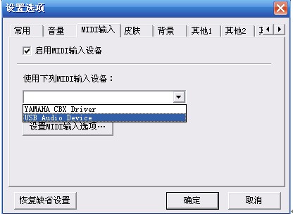
Firstly,we should program the arduino,attach the MIDI breadout to the arduinoboard,connect the USBtoMIDI cable to PC and MIDI breadout board,the PC can recognize the device,then open the HappyEO,press the buttom “option”,select the common item and select the USB Audio Device as the output device.Then select the MIDI input item and select the USB Audio Device item.
If you has select the USB AUDIO DEVICE item,select Wave table software synthesizers as the output device, you can hear the music with the earphone from the arduino+MIDI Breakout board. And you can see the LEDs is flash.
If you select the USB AUDIO DEVICE as the output device,HappyEO can send the data and command to arduino when wo press the keyboard,the led will falsh when it receive data.
Test code
- The code blew is standard code,you can change the code on the basis of your requirement.
<syntaxhighlight lang="c">
// defines for MIDI Shield components only
- define KNOB1 0
- define KNOB2 1
- define BUTTON1 2
- define BUTTON2 3
- define BUTTON3 4
- define STAT1 7
- define STAT2 6
- define OFF 1
- define ON 2
- define WAIT 3
byte incomingByte;
byte note; byte velocity; int pot;
byte byte1; byte byte2; byte byte3;
int action=2; //1 =note off ; 2=note on ; 3= wait
void setup() {
pinMode(STAT1,OUTPUT);
pinMode(STAT2,OUTPUT);
pinMode(BUTTON1,INPUT);
pinMode(BUTTON2,INPUT); pinMode(BUTTON3,INPUT);
digitalWrite(BUTTON1,HIGH); digitalWrite(BUTTON2,HIGH); digitalWrite(BUTTON3,HIGH);
for(int i = 0;i < 10;i++) // flash MIDI Sheild LED's on startup
{
digitalWrite(STAT1,HIGH); digitalWrite(STAT2,LOW); delay(30); digitalWrite(STAT1,LOW); digitalWrite(STAT2,HIGH); delay(30);
}
digitalWrite(STAT1,HIGH);
digitalWrite(STAT2,HIGH);
//start serial with midi baudrate 31250
Serial.begin(31250);
}
void loop () {
//*************** MIDI OUT ***************//
pot = analogRead(0);
note = pot/8; // convert value to value 0-127 if(button(BUTTON1) || button(BUTTON2) || button(BUTTON3))
{
Midi_Send(0x90,note,0x45);
while(button(BUTTON1) || button(BUTTON2) || button(BUTTON3));
}
//*************** MIDI LOOPBACK ******************//
if(Serial.available() > 0)
{
byte1 = Serial.read(); byte2 = Serial.read(); byte3 = Serial.read();
Midi_Send(byte1, byte2, byte3);
}
//*************** MIDI IN ***************// if (Serial.available() > 0) { // read the incoming byte: incomingByte = Serial.read();
// wait for as status-byte, channel 1, note on or off if (incomingByte== 144) // Note on
{
action = OFF;
}
else if (incomingByte== 128) // Note off
{
action = ON;
}
else if (note==0 && action != WAIT) // note on, wait for note value
{
note=incomingByte;
}
else if (note!=0 && action != WAIT) // velocity
{
velocity=incomingByte;
if(action == ON){ Midi_Send(0x90,note,velocity);
}
if(action == OFF){ Midi_Send(0x80,note,velocity);
} note=0; velocity=0; action=WAIT;
}
else{
}
}
}
void Midi_Send(byte cmd, byte data1, byte data2) { Serial.print(cmd, BYTE);
Serial.print(data1, BYTE);
Serial.print(data2, BYTE);
}
void blink(){
digitalWrite(STAT1, HIGH);
delay(100); digitalWrite(STAT1, LOW); delay(100); }
char button(char button_num)
{
return (!(digitalRead(button_num)));
}
</syntaxhighlight>
FAQ
Please list your question here:
Support
If you have questions or other better design ideas, you can go to our forum to discuss or creat a ticket for your issue at linksprite support.
Resources
How to buy
Here to buy MIDI Shield for Arduino on store
See Also
Other related products and resources.
Licensing
This documentation is licensed under the Creative Commons Attribution-ShareAlike License 3.0 Source code and libraries are licensed under GPL/LGPL, see source code files for details.


