Difference between revisions of "Rover: WiFi Video Streaming Robot"
(→Resources) |
Qian.zhang (talk | contribs) (→Resources) |
||
| (22 intermediate revisions by 3 users not shown) | |||
| Line 36: | Line 36: | ||
| − | [[File:Rover controlboard.jpg]] | + | [[File:Rover controlboard new.jpg]] |
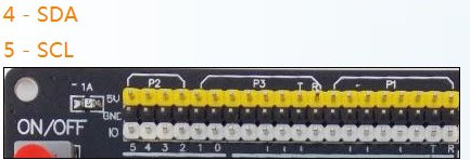
*Hello, I am trying to connect a I2C LCD2004 display to the linksprite Rover robot. What pin on the core I/O board do I connect the SCL and SDA pins of the LCD display to ? On an Uno it is (Analog) pin 4 and ping 5. | *Hello, I am trying to connect a I2C LCD2004 display to the linksprite Rover robot. What pin on the core I/O board do I connect the SCL and SDA pins of the LCD display to ? On an Uno it is (Analog) pin 4 and ping 5. | ||
| Line 43: | Line 43: | ||
== Mechanic Dimensions == | == Mechanic Dimensions == | ||
| − | + | [[File:Assemblystep 21 en.jpg]] | |
| − | |||
| − | |||
| − | |||
== Usage == | == Usage == | ||
| Line 58: | Line 55: | ||
'''Control Board:''' | '''Control Board:''' | ||
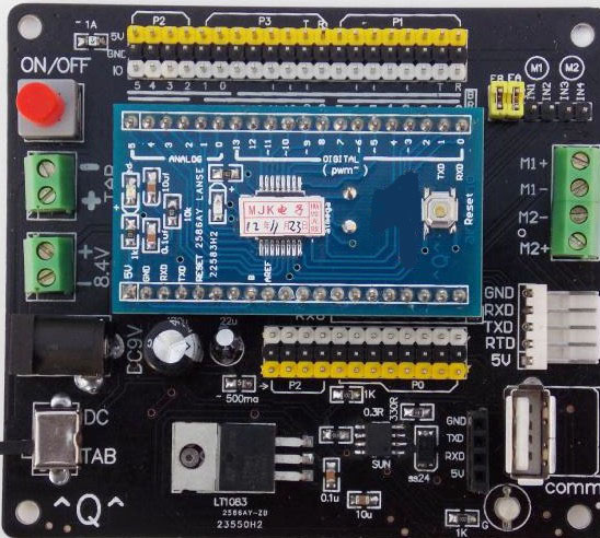
| − | [[File:Rover controlboard.jpg]] | + | [[File:Rover controlboard new.jpg]] |
The Arduino control board on the Rover is "Arduino Diecimila or Duemilanove W/Atmea168", when you use Arduino IDE to select the board type. | The Arduino control board on the Rover is "Arduino Diecimila or Duemilanove W/Atmea168", when you use Arduino IDE to select the board type. | ||
| Line 98: | Line 95: | ||
[[File:Assemblystep 10.jpg]] | [[File:Assemblystep 10.jpg]] | ||
| − | |||
| − | |||
=== Programming === | === Programming === | ||
The Arduino control board on the Rover is "Arduino Diecimila or Duemilanove W/Atmea168". | The Arduino control board on the Rover is "Arduino Diecimila or Duemilanove W/Atmea168". | ||
| + | |||
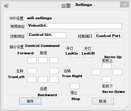
| + | === WiFi Robot Setting === | ||
| + | |||
| + | [[File:WiFi Robot Setting.jpg]] | ||
== FAQ == | == FAQ == | ||
| Line 121: | Line 120: | ||
***I also uploaded here: | ***I also uploaded here: | ||
****https://www.dropbox.com/s/56amqvf9bmcprz1/Rover issue.mp4 | ****https://www.dropbox.com/s/56amqvf9bmcprz1/Rover issue.mp4 | ||
| + | **A: | ||
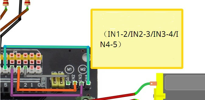
| + | We tried to watch the video, and thought that INT1/INT2/INT3/INT4 are not connected. Please confirm. | ||
| + | |||
| + | [[File:Rover jumper.jpg]] | ||
| + | *What's the username and password of the router? | ||
| + | **The username is admin, and password is 123456. | ||
| + | ***Thanks for the enlightenment. FYI: the username is not “admin” for either the ssh or webpage login, it is “root”, | ||
| + | *I recently purchased a LinkSprite Rover from you and everything worked fine until I tried to transmit from the Arduino through the TL-WR703N. I can send the Rover commands but I cannot receive anything from it through the TL-WR703N. To confirm the problem I create a simple sketch that sends an 'x' character out every second using "Serial.write("x");". I can see the output form the sketch when the Rover is connected to my computer USB port. I then added a control port to ser2net in the /etc/init.d/wificar script by changing the line "ser2net" to "ser2net -p 20000". I then telnetted to the control port and I could see my socket connection from my computer and I could see the tcp input from my socket connection using "monitor tcp 2001" but I can see nothing from the arduino when using "monitor term 2001". It's as if there is no connection from the Tx pin on the Arduino to the TL-WR703N. I tried two different USB cables. I think that this TL-WR703N WiFi router may be defective. What do you suggest? I see that you have both "TL-WR703N Clone With OPENWRT, USB Camera Support, TTL UART" and "TL-WR703N Portable Mini 150M 802.11n WiFi Wireless 3G Router" for sale. | ||
| + | **I opened up the TL-WR703N and found that LinkSprite just wired the TP_IN pin of the AR9331 directly to the micro USB connector which then connects directly to the Tx pin on ATMega168. The ATMega is 5V TTL and the Atheros AR9331 is 3.3V TTL. From what I have read the Atheros AR9331 does not tolerate 5V TTL on it TP_IN pin. | ||
| + | ** I created a cable to connect the TL-WR703N micro USB connector to the CP2102 TTL to USB cable that came with the kit and the TL-WR703N OpenWRT console works fine on my computer COM port. So the TP_IN pin on the AR9331 is ok. The Arduino Tx pin can also send data through same TTL to USB cable to my computer. The problem is that I cannot get serial data from the Arduino Tx pin to the AR9331 TP_IN pin. I suspect that there is either a problem with ser2net or some incompatabilty between how the Arduino sends and the AR9331 receives serial data. Any information about this issue would be much appreciated. | ||
| + | **Update- I figured it out... I had to remove the line "ttyATH0::askfirst:/bin/ash --login" from the /etc/inittab file to prevent OpenWRT from using the serial port as the console. | ||
| + | * If I want capacitors to reduce electrical noise and/or protect the motors, what value should I use? | ||
| + | ** 100uF, rating is 25V. | ||
| + | *can the board be used as a normal uno arduino board for other projects. does it have a removable atmel chip for reprogramming. | ||
| + | **It is just a mini Arduino compatible board. It can be used for other projects, but not removable chip. It is a STM chip. | ||
| + | *does it come with a shield so I can modify and add more sensors? also what is the speed in MHz of the board and power supply (3 or 5 volts) | ||
| + | **No. it doesn't come with a shield. But you can use jumper wires to add more sensors. The crystal is 16Mhz, and power supply is 5V. | ||
== Support == | == Support == | ||
| − | If you have questions or other better design ideas, you can go to our [http:// | + | If you have questions or other better design ideas, you can go to our [http://forum.linksprite.com/index.php?/forum/32-rover/ forum] to discuss. |
== Resources == | == Resources == | ||
*[http://linksprite.com/wiki/index.php5?title=Tutorial_of_compiling_OpenWRT Tutorial of Compiling OpenWRT ] | *[http://linksprite.com/wiki/index.php5?title=Tutorial_of_compiling_OpenWRT Tutorial of Compiling OpenWRT ] | ||
| − | *[https://s3.amazonaws.com/linksprite/robot/ | + | *[https://s3.amazonaws.com/linksprite/robot/Rover+English/RoverPC_English.zip Rover PC software] |
| − | *[https://s3.amazonaws.com/linksprite/robot/ | + | *[https://s3.amazonaws.com/linksprite/robot/Rover+English/Source+file+WifRobot.zip Source files of Rover PC software] |
| − | *[https://s3.amazonaws.com/ | + | *[https://s3.amazonaws.com/linksprite/robot/Rover+English/RoverBot_Arduino_Sample_Code.ino Arduino Sample Code] |
| + | *[https://s3.amazonaws.com/pcduino/Images/v2/VideoRobot9V/WiFiRobot.apk Android apk] | ||
| + | *[http://www.linksprite.com/wp-content/uploads/2015/02/rover-assembling-instruction.pdf Tutorial] | ||
== How to buy == | == How to buy == | ||
Latest revision as of 02:01, 3 February 2015
Contents
Introduction
Rover is LinkSprite's new robot platform. It has the main control board, an Arduino compatible core board, an USB camera, an ultrasonic sensor, and TL-WR703N WiFi router reflashed with OPENWRT firmware, and the basic mechanical platform. The mechanical control part is implemented on the Arduino compatible core board (this is included on the kit), while the video streaming part is implemented on the TL-WR703N Wifi router using OPENWRT. We provide the source files of Arduino, and the PC control software. Users can also learn OPENWRT using this platform.
Features
Application Ideas
Cautions
Schematic
Specification
Pin definition and Rating
- Hello, I am trying to connect a I2C LCD2004 display to the linksprite Rover robot. What pin on the core I/O board do I connect the SCL and SDA pins of the LCD display to ? On an Uno it is (Analog) pin 4 and ping 5.
Mechanic Dimensions
Usage
Hardware Installation
Control Board:
The Arduino control board on the Rover is "Arduino Diecimila or Duemilanove W/Atmea168", when you use Arduino IDE to select the board type.
Camera/Servo:
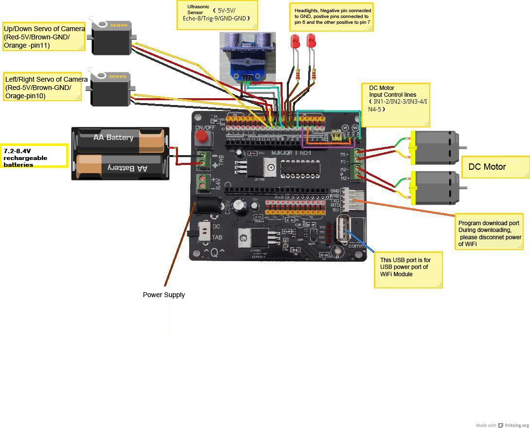
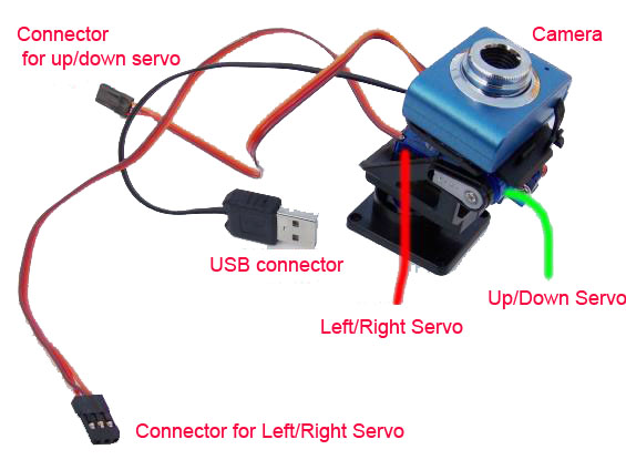
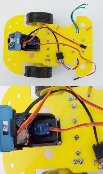
The servo platform has two part: up/down and left/right. Both directions can do 180 degree rotation. The USB camera is plugged into the WiFi module. Up/down servo connector is connected to pin 11 of the control board, and left/right servo connector is connected to pin 10 of the control board.
Ultrasonic Sensor:
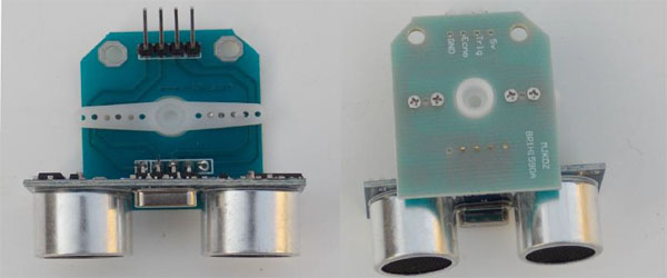
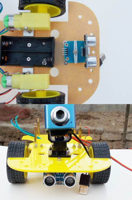
The ultrasonic sensor is used to detect object and avoid collision. This sensor has 4 pins: 5V is connected to 5V pin of the control board; Trig is connected to pin 9 of the control board; Echo is connected to pin 9 of the control board. GND is connected to GND of the control board.
We didn't provide sample of how to use the ultrasonic sensor breakout included on the Rover kit. However, the user can find the information at here.
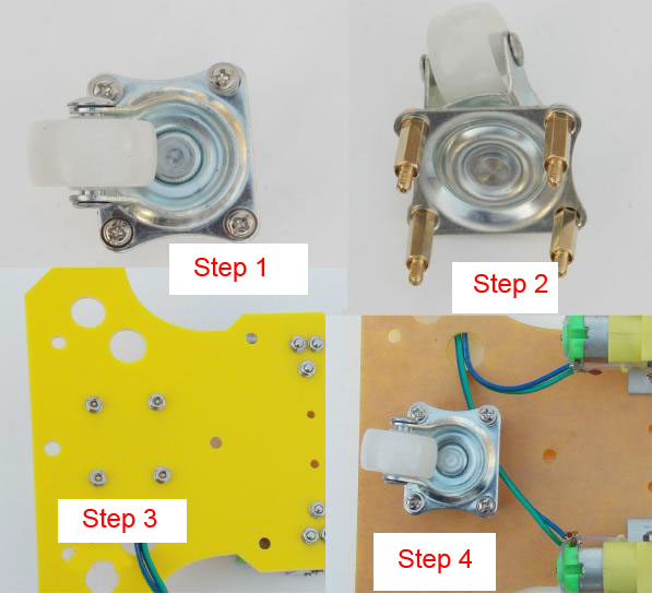
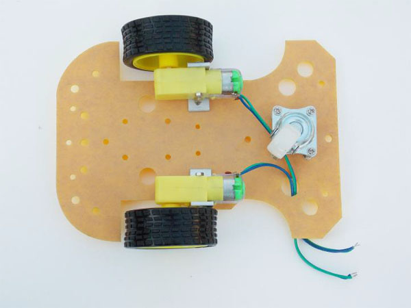
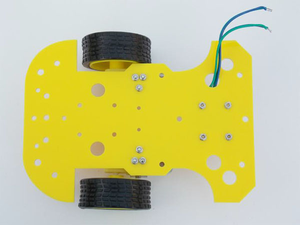
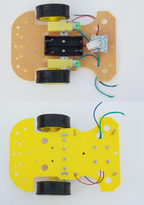
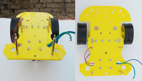
Mechanical Assembly Steps
Programming
The Arduino control board on the Rover is "Arduino Diecimila or Duemilanove W/Atmea168".
WiFi Robot Setting
FAQ
Please list your question here:
- Hi. I want know which components are included in your package. Is included the Arduino board? Are included mechanical and electrical components. Is the board already assembled? Thanks for your responce.
- It includes the Arduino compatible board, main servo control board, ultrasonic sensor, and the mechnical platform. But the batteries are NOT included.
- My issue now is that I can only get the Camera to load, and I can move the camera, up down left and right. I cannot get the Wheels to move. I have connect the wire to the motor and connect the other end to M1 -/+ and M2 -/+. I have also tried different combinations but nothing works. My question is this.... right now I dont have a battery, so its plugged into DC input adapter you sent me. Is there something that prevents the wheels from moving unless its in battery mode. Otherwise something seems to be wrong in the code or something. Also i have changed in the setting the Up, Down, Left and Right in the software to reflect the code of "a" "b" "c" and "d". I am very confused as to whats happening. Here is a video of what i am doing.....
- I dont know if you can see a video but here it is....
- Watch this...
- or here
- I also uploaded here:
- A:
- I dont know if you can see a video but here it is....
We tried to watch the video, and thought that INT1/INT2/INT3/INT4 are not connected. Please confirm.
- What's the username and password of the router?
- The username is admin, and password is 123456.
- Thanks for the enlightenment. FYI: the username is not “admin” for either the ssh or webpage login, it is “root”,
- The username is admin, and password is 123456.
- I recently purchased a LinkSprite Rover from you and everything worked fine until I tried to transmit from the Arduino through the TL-WR703N. I can send the Rover commands but I cannot receive anything from it through the TL-WR703N. To confirm the problem I create a simple sketch that sends an 'x' character out every second using "Serial.write("x");". I can see the output form the sketch when the Rover is connected to my computer USB port. I then added a control port to ser2net in the /etc/init.d/wificar script by changing the line "ser2net" to "ser2net -p 20000". I then telnetted to the control port and I could see my socket connection from my computer and I could see the tcp input from my socket connection using "monitor tcp 2001" but I can see nothing from the arduino when using "monitor term 2001". It's as if there is no connection from the Tx pin on the Arduino to the TL-WR703N. I tried two different USB cables. I think that this TL-WR703N WiFi router may be defective. What do you suggest? I see that you have both "TL-WR703N Clone With OPENWRT, USB Camera Support, TTL UART" and "TL-WR703N Portable Mini 150M 802.11n WiFi Wireless 3G Router" for sale.
- I opened up the TL-WR703N and found that LinkSprite just wired the TP_IN pin of the AR9331 directly to the micro USB connector which then connects directly to the Tx pin on ATMega168. The ATMega is 5V TTL and the Atheros AR9331 is 3.3V TTL. From what I have read the Atheros AR9331 does not tolerate 5V TTL on it TP_IN pin.
- I created a cable to connect the TL-WR703N micro USB connector to the CP2102 TTL to USB cable that came with the kit and the TL-WR703N OpenWRT console works fine on my computer COM port. So the TP_IN pin on the AR9331 is ok. The Arduino Tx pin can also send data through same TTL to USB cable to my computer. The problem is that I cannot get serial data from the Arduino Tx pin to the AR9331 TP_IN pin. I suspect that there is either a problem with ser2net or some incompatabilty between how the Arduino sends and the AR9331 receives serial data. Any information about this issue would be much appreciated.
- Update- I figured it out... I had to remove the line "ttyATH0::askfirst:/bin/ash --login" from the /etc/inittab file to prevent OpenWRT from using the serial port as the console.
- If I want capacitors to reduce electrical noise and/or protect the motors, what value should I use?
- 100uF, rating is 25V.
- can the board be used as a normal uno arduino board for other projects. does it have a removable atmel chip for reprogramming.
- It is just a mini Arduino compatible board. It can be used for other projects, but not removable chip. It is a STM chip.
- does it come with a shield so I can modify and add more sensors? also what is the speed in MHz of the board and power supply (3 or 5 volts)
- No. it doesn't come with a shield. But you can use jumper wires to add more sensors. The crystal is 16Mhz, and power supply is 5V.
Support
If you have questions or other better design ideas, you can go to our forum to discuss.
Resources
- Tutorial of Compiling OpenWRT
- Rover PC software
- Source files of Rover PC software
- Arduino Sample Code
- Android apk
- Tutorial
How to buy
See Also
Other related products and resources.
Licensing
This documentation is licensed under the Creative Commons Attribution-ShareAlike License 3.0 Source code and libraries are licensed under GPL/LGPL, see source code files for details.
