Difference between revisions of "Linear/Slide Potentiometer Module"
(→Introduction) |
|||
| (13 intermediate revisions by 3 users not shown) | |||
| Line 1: | Line 1: | ||
| − | + | ==Introduction== | |
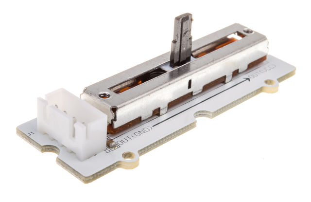
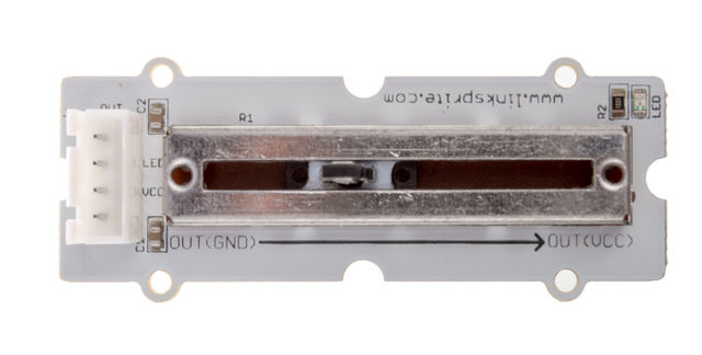
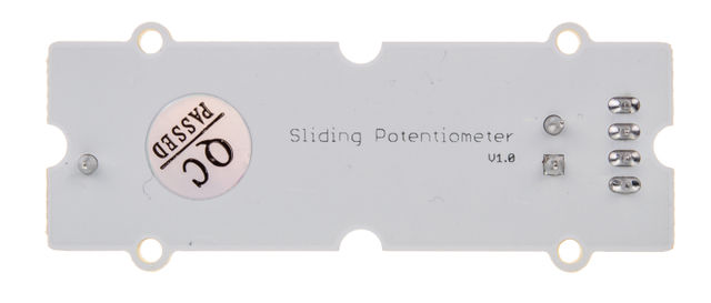
| + | The slide potentiometer is a linear variable resistor with a total resistance of 10k. When you move the lever from one side to the other, its output voltage will range from 0 V to the VCC you apply. It has four pins, 3 of which are connected to VCC, GND and the ADC IN on the slide, while the remaining pin is connected to a red indicator LED. You can use the indicator LED to visually display the change on the potentiometer. | ||
| + | |||
| + | |||
| + | [[File:LinearSlide 118101006 first.jpg| 640px]] | ||
| + | |||
| + | [[File:LinearSlide 118101006 second.jpg| 640px]] | ||
| + | |||
| + | [[File:LinearSlide 118101006 third.jpg| 640px]] | ||
| + | |||
| + | == Features == | ||
| + | |||
| + | Dimensions: 60.0×24.0×20.0mm | ||
| + | |||
| + | Net weight: 8g | ||
| + | |||
| + | == Dimension == | ||
| + | |||
| + | [[File:sliding potentiometer dimension.jpg]] | ||
== Schematics == | == Schematics == | ||
*[https://s3.amazonaws.com/linksprite/LinkerKit/sliding+protentiometer.pdf Schematics] | *[https://s3.amazonaws.com/linksprite/LinkerKit/sliding+protentiometer.pdf Schematics] | ||
| + | |||
| + | ==Application Ideas== | ||
| + | |||
| + | <syntaxhighlight lang="c"> | ||
| + | |||
| + | int adcPin = A0; // select the input pin for the potentiometer | ||
| + | int ledPin = A1; // select the pin for the LED | ||
| + | int adcIn = 0; // variable to store the value coming from the sensor | ||
| + | |||
| + | void setup() { | ||
| + | Serial.begin(9600); // init serial to 9600b/s | ||
| + | pinMode(ledPin, OUTPUT); // set ledPin to OUTPUT | ||
| + | Serial.println("Sliding Potentiometer Test Code!!"); | ||
| + | } | ||
| + | |||
| + | void loop() { | ||
| + | // read the value from the sensor: | ||
| + | adcIn = analogRead(adcPin); | ||
| + | if(adcIn >= 500) digitalWrite(ledPin,HIGH); // if adc in > 500, led light | ||
| + | else digitalWrite(ledPin, LOW); | ||
| + | Serial.println(adcIn); | ||
| + | delay(100); | ||
| + | } | ||
| + | |||
| + | </syntaxhighlight> | ||
| + | |||
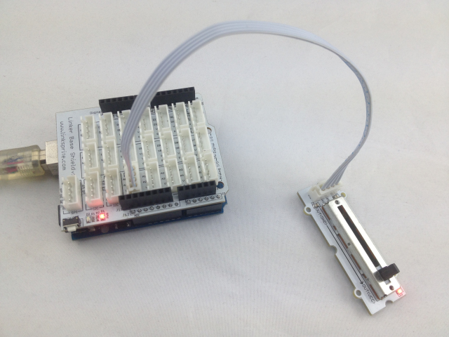
| + | Here Linear/Slide Potentiometer Module is connected to [A0 A1 V G]. | ||
| + | |||
| + | |||
| + | [[File:Slide Link.jpg]] | ||
| + | |||
| + | ==How to buy== | ||
| + | Here to buy Linear/Slide Potentiometer Module on [http://store.linksprite.com/linear-slide-potentiometer-of-linker-kit-for-pcduino-arduino/ store] | ||
Latest revision as of 11:11, 18 July 2016
Introduction
The slide potentiometer is a linear variable resistor with a total resistance of 10k. When you move the lever from one side to the other, its output voltage will range from 0 V to the VCC you apply. It has four pins, 3 of which are connected to VCC, GND and the ADC IN on the slide, while the remaining pin is connected to a red indicator LED. You can use the indicator LED to visually display the change on the potentiometer.
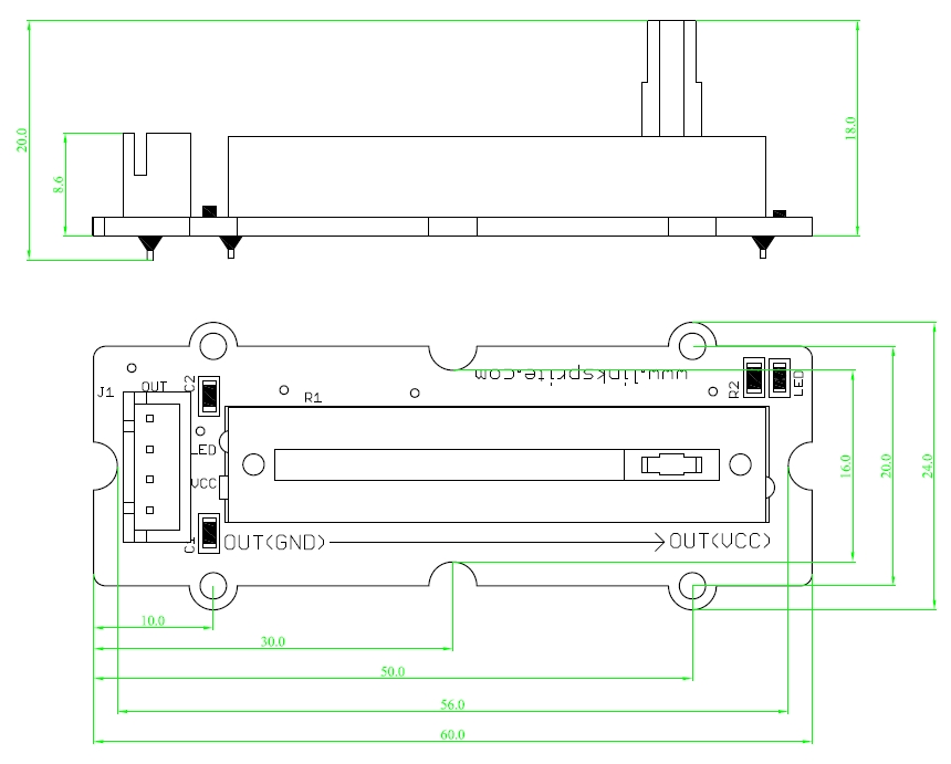
Features
Dimensions: 60.0×24.0×20.0mm
Net weight: 8g
Dimension
Schematics
Application Ideas
<syntaxhighlight lang="c">
int adcPin = A0; // select the input pin for the potentiometer int ledPin = A1; // select the pin for the LED int adcIn = 0; // variable to store the value coming from the sensor
void setup() {
 Serial.begin(9600);        // init serial to 9600b/s
 pinMode(ledPin, OUTPUT);    // set ledPin to OUTPUT
 Serial.println("Sliding Potentiometer Test Code!!");
}
void loop() {
 // read the value from the sensor:
 adcIn = analogRead(adcPin);
 if(adcIn >= 500)  digitalWrite(ledPin,HIGH);  // if adc in > 500, led light
 else digitalWrite(ledPin, LOW);
 Serial.println(adcIn);
 delay(100);
}
</syntaxhighlight>
Here Linear/Slide Potentiometer Module is connected to [A0 A1 V G].
How to buy
Here to buy Linear/Slide Potentiometer Module on store
