Difference between revisions of "Tilt Module"
(Created page with "<syntaxhighlight lang="c"> /* Tilt Turns on and off a T010111 LED Module connected to O0 (digital pin 11), triggered by a T000190 Tilt Sensor attached to I0 (analog pin ...") |
(→Introduction) |
||
| (17 intermediate revisions by 3 users not shown) | |||
| Line 1: | Line 1: | ||
| − | + | ==Introduction== | |
| − | + | The Linker Tilt Module is the equivalent of a button, and is used as a digital input. Inside the tilt switch is a pair of balls that make contact with the pins when the case is upright. Tilt the case over and the balls don't touch, thus not making a connection. It is wired to the SIG line, NC is not used on this kit. | |
| − | + | ||
| + | [[File:Tilt 118101004 first.jpg| 500px]] | ||
| + | |||
| + | [[File:Tilt 118101004 second.jpg| 500px]] | ||
| − | + | [[File:Tilt 118101004 third.jpg| 500px]] | |
| − | |||
| − | + | == Features == | |
| − | |||
| − | |||
| − | |||
| − | |||
| − | |||
| − | + | Dimensions: 27.9×25.4×10.6mm | |
| − | + | Net weight: 3.6g | |
| − | + | == Dimension == | |
| − | |||
| − | |||
| − | |||
| − | |||
| − | |||
| − | |||
| − | |||
| − | |||
| − | |||
| − | |||
| − | |||
| − | + | [[File:tilt dimension.jpg]] | |
| − | |||
| − | |||
| − | |||
| − | // | + | == Schematics == |
| − | + | *[https://s3.amazonaws.com/linksprite/LinkerKit/Linker+Tilt.pdf Schematics] | |
| − | + | ==Application Ideas== | |
| − | |||
| − | |||
| − | |||
| − | |||
| − | |||
| − | + | <syntaxhighlight lang="c"> | |
| − | |||
| − | |||
| − | + | int ledPin = 13; | |
| − | + | int switchPin = 7; | |
| − | + | int val = 0; | |
| − | + | void setup() | |
| − | + | { | |
| − | + | pinMode(ledPin,OUTPUT); | |
| − | + | pinMode(switchPin,INPUT); | |
| − | |||
| − | |||
| − | |||
} | } | ||
| + | void loop() | ||
| + | { | ||
| + | //digitlRead(switchPin,HIGH) | ||
| + | val = digitalRead(switchPin); | ||
| + | if (HIGH == val) digitalWrite(ledPin,HIGH); | ||
| + | else digitalWrite(ledPin,LOW); | ||
| + | } | ||
| + | |||
</syntaxhighlight> | </syntaxhighlight> | ||
| + | |||
| + | [[File:Tilt link.jpg]] | ||
| + | |||
| + | ==How to buy== | ||
| + | Here to buy Tilt Module on [http://store.linksprite.com/tilt-module-of-linker-kit-for-pcduino-arduino/ store] | ||
Latest revision as of 08:17, 14 September 2016
Introduction
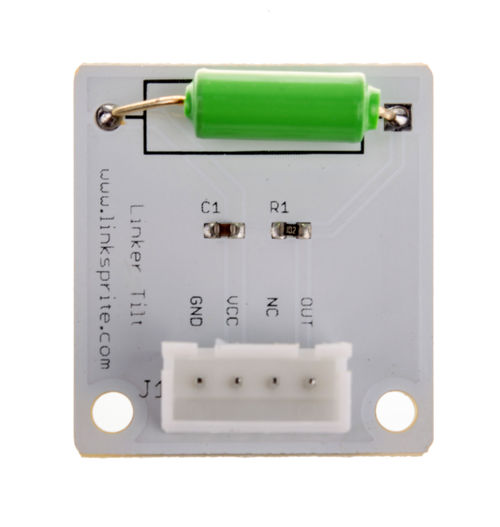
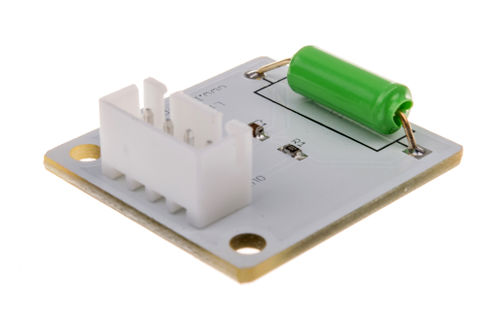
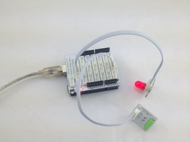
The Linker Tilt Module is the equivalent of a button, and is used as a digital input. Inside the tilt switch is a pair of balls that make contact with the pins when the case is upright. Tilt the case over and the balls don't touch, thus not making a connection. It is wired to the SIG line, NC is not used on this kit.
Features
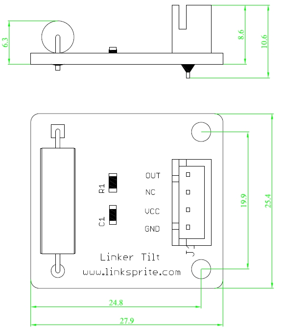
Dimensions: 27.9×25.4×10.6mm
Net weight: 3.6g
Dimension
Schematics
Application Ideas
<syntaxhighlight lang="c">
int ledPin = 13; int switchPin = 7; int val = 0; void setup() {
 pinMode(ledPin,OUTPUT);
 pinMode(switchPin,INPUT);
} void loop() {
 //digitlRead(switchPin,HIGH)
 val = digitalRead(switchPin);
 if (HIGH == val)  digitalWrite(ledPin,HIGH);
 else  digitalWrite(ledPin,LOW);
}
</syntaxhighlight>
How to buy
Here to buy Tilt Module on store
