Difference between revisions of "Advanced Sensors Kit for Arduino"
| (24 intermediate revisions by the same user not shown) | |||
| Line 74: | Line 74: | ||
| [[File:ky011.jpg | 300px]] | | [[File:ky011.jpg | 300px]] | ||
| | | | ||
| + | This is a dual color LED module. | ||
*[https://s3.amazonaws.com/linksprite/Arduino_kits/advanced_sensors_kit/KY011+code.pdf Arduino Sample Code] | *[https://s3.amazonaws.com/linksprite/Arduino_kits/advanced_sensors_kit/KY011+code.pdf Arduino Sample Code] | ||
|- | |- | ||
| Line 80: | Line 81: | ||
| [[File:ky012.jpg | 250px]] | | [[File:ky012.jpg | 250px]] | ||
| | | | ||
| + | This is a nonactive buzzer module. | ||
*[https://s3.amazonaws.com/linksprite/Arduino_kits/advanced_sensors_kit/KY012+code.pdf Arduino Sample Code] | *[https://s3.amazonaws.com/linksprite/Arduino_kits/advanced_sensors_kit/KY012+code.pdf Arduino Sample Code] | ||
|- | |- | ||
| KY013: | | KY013: | ||
| − | Analog | + | Analog Temperature Sensor |
| [[File:ky013.jpg | 250px]] | | [[File:ky013.jpg | 250px]] | ||
| | | | ||
| + | This is an analog temperature sensor that outputs it voltage in proportional to the temperature. | ||
*[https://s3.amazonaws.com/linksprite/Arduino_kits/advanced_sensors_kit/KY013+code.pdf Arduino Sample Code] | *[https://s3.amazonaws.com/linksprite/Arduino_kits/advanced_sensors_kit/KY013+code.pdf Arduino Sample Code] | ||
|- | |- | ||
| Line 92: | Line 95: | ||
| [[File:ky015.jpg | 250px]] | | [[File:ky015.jpg | 250px]] | ||
| | | | ||
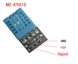
| + | This DHT11 Temperature and Humidity Sensor features a calibrated digital signal output with the temperature and humidity sensor complex,ensureing the high reliability and excellent long-term stability. A high-performance 8-bit microcontroller is connected. This sensor includes a resistive element and a sense of wet NTC temperature measuring devices. It has excellent quality, fast response, anti-interference ability and high cost performance advantages. | ||
*[https://s3.amazonaws.com/linksprite/Arduino_kits/advanced_sensors_kit/KY015+code.pdf Arduino Sample Code] | *[https://s3.amazonaws.com/linksprite/Arduino_kits/advanced_sensors_kit/KY015+code.pdf Arduino Sample Code] | ||
|- | |- | ||
| Line 98: | Line 102: | ||
| [[File:ky016.jpg | 250px]] | | [[File:ky016.jpg | 250px]] | ||
| | | | ||
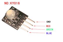
| + | This is a through the hole three-color LED module that can make any color we want by combing different intensities of Red, Blue and Green. | ||
*[https://s3.amazonaws.com/linksprite/Arduino_kits/advanced_sensors_kit/KY016+code.pdf Arduino Sample Code] | *[https://s3.amazonaws.com/linksprite/Arduino_kits/advanced_sensors_kit/KY016+code.pdf Arduino Sample Code] | ||
|- | |- | ||
| Line 104: | Line 109: | ||
| [[File:ky017.jpg | 250px]] | | [[File:ky017.jpg | 250px]] | ||
| | | | ||
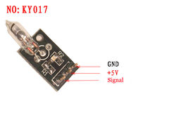
| + | A tilt switch that can turn on and off depending on the tilt position. The switch is mercury. | ||
*[https://s3.amazonaws.com/linksprite/Arduino_kits/advanced_sensors_kit/KY017+code.pdf Arduino Sample Code] | *[https://s3.amazonaws.com/linksprite/Arduino_kits/advanced_sensors_kit/KY017+code.pdf Arduino Sample Code] | ||
|- | |- | ||
| Line 110: | Line 116: | ||
| [[File:ky018.jpg | 250px]] | | [[File:ky018.jpg | 250px]] | ||
| | | | ||
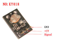
| + | Photoresistors are semiconductor photosensitive devices, in addition to having high sensitivity, fast response, consistent with the spectral characteristics and value of good features | ||
| + | Under a high temperature, and humidity in harsh environments, it also can maintain a high degree of stability and reliability | ||
| + | Wide pan used cameras, solar garden lights, lawn, detectors, clock, music, cups, gift boxes, mini-night light, light voice switches, lights automatically switch toys and a variety of light control, light control lighting, lamps and other light automatic opening control field | ||
*[https://s3.amazonaws.com/linksprite/Arduino_kits/advanced_sensors_kit/KY018+code.pdf Arduino Sample Code] | *[https://s3.amazonaws.com/linksprite/Arduino_kits/advanced_sensors_kit/KY018+code.pdf Arduino Sample Code] | ||
|- | |- | ||
| Line 116: | Line 125: | ||
| [[File:ky019.jpg | 250px]] | | [[File:ky019.jpg | 250px]] | ||
| | | | ||
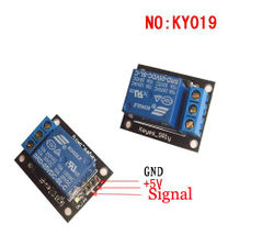
| + | This is 1 channel relay module with the following spec: | ||
| + | *Can be used as microcontroller development board module can be used as home appliance control | ||
| + | *5 V-12V to TTL control signal | ||
| + | *The control signal DC or AC, 220V AC load can be controlled. | ||
| + | *There is a normally open and one normally closed contact | ||
| + | *A power indicator light | ||
| + | *A control indicator, pull off, disconnect does not shine | ||
| + | *Aransistor drive to increase the relay coil control pins high impedance. | ||
| + | *A control pin has a pull-down circuit to prevent malfunction relay vacant | ||
| + | |||
*[https://s3.amazonaws.com/linksprite/Arduino_kits/advanced_sensors_kit/KY019+code.pdf Arduino Sample Code] | *[https://s3.amazonaws.com/linksprite/Arduino_kits/advanced_sensors_kit/KY019+code.pdf Arduino Sample Code] | ||
|- | |- | ||
| Line 122: | Line 141: | ||
| [[File:ky020.jpg | 250px]] | | [[File:ky020.jpg | 250px]] | ||
| | | | ||
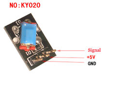
| + | Tilt switch module and a digital interface, built-in 13 LED build a simple circuit to produce tilt warning lamp 13 comes with digital interfaces of the LED, the tilt switch sensor interface to access digital 3,when the tilt open Off sensor senses a key signal, LED lights, otherwise off. | ||
*[https://s3.amazonaws.com/linksprite/Arduino_kits/advanced_sensors_kit/KY020+code.pdf Arduino Sample Code] | *[https://s3.amazonaws.com/linksprite/Arduino_kits/advanced_sensors_kit/KY020+code.pdf Arduino Sample Code] | ||
|- | |- | ||
| Line 128: | Line 148: | ||
| [[File:ky021.jpg | 250px]] | | [[File:ky021.jpg | 250px]] | ||
| | | | ||
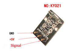
| + | Reed module and the interface comes with digital 13 LED build a simple circuit to produce a Reed warning lamp 13 comes with digital interfaces of the LED, the Reed sensor access number 3 interface, when Reed sensors Sensed a key signal, LED lights, otherwise off. | ||
*[https://s3.amazonaws.com/linksprite/Arduino_kits/advanced_sensors_kit/KY020+code.pdf Arduino Sample Code] | *[https://s3.amazonaws.com/linksprite/Arduino_kits/advanced_sensors_kit/KY020+code.pdf Arduino Sample Code] | ||
|- | |- | ||
| Line 134: | Line 155: | ||
| [[File:ky022.jpg | 300px]] | | [[File:ky022.jpg | 300px]] | ||
| | | | ||
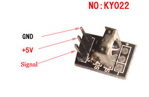
| + | This is the infrared receiver module, with the following features: | ||
| + | *The infrared receiver module is 1838 Infrared receiver | ||
| + | *Acceptance angle: 90 °, | ||
| + | *Operating voltage: 7-5.5V. | ||
| + | *Frequency: 37.9KHZ, | ||
| + | *Receiving distance: 18Meter. | ||
| + | *Using inside and outside the double-shielded package structure | ||
| + | *Anti-light, electromagnetic interference capability, built-in infrared dedicated IC Can in 500 LUX Light intensity to work properly. | ||
| + | *Widely used in: stereo, TV, VCR, disc players, set-top boxes, digital photo frame, car audio, remote control toys, satellite receiver, hard disk player, air conditioners, heaters, fans, lighting and other household appliances. | ||
| + | |||
*[https://s3.amazonaws.com/linksprite/Arduino_kits/advanced_sensors_kit/InfraredReceiver.rar Arduino Sample Code] | *[https://s3.amazonaws.com/linksprite/Arduino_kits/advanced_sensors_kit/InfraredReceiver.rar Arduino Sample Code] | ||
|- | |- | ||
| Line 140: | Line 171: | ||
| [[File:ky023.jpg | 300px]] | | [[File:ky023.jpg | 300px]] | ||
| | | | ||
| + | On the principle, the control rod can be considered that it is organized by the two potentiometer and a button.When using, it can connect with Arduino sensor shield,and connect Arduino corresponding pins through Arduino sensor cables. It as the following spec: | ||
| + | *Directional movements are simply two potentiometers - one for each axis | ||
| + | *Compatible with Arduino interface | ||
| + | *The biaxial XY Joystick Module KY-023 applies ARDUINO | ||
| + | *Dimensions: 1.57 in x 1.02 in x 1.26 in (4.0 cm x 2.6 cm x 3.2 cm) | ||
| + | *5 Pin | ||
*[https://s3.amazonaws.com/linksprite/Arduino_kits/advanced_sensors_kit/KY023+code.pdf Arduino Sample Code] | *[https://s3.amazonaws.com/linksprite/Arduino_kits/advanced_sensors_kit/KY023+code.pdf Arduino Sample Code] | ||
|- | |- | ||
| Line 146: | Line 183: | ||
| [[File:ky024.jpg | 300px]] | | [[File:ky024.jpg | 300px]] | ||
| | | | ||
| + | Linear Hall magnetic module and a digital interface, built-in 13 LED build a simple circuit to | ||
| + | produce a magnetic field warning lamp 13 comes with digital interfaces of the LED, the linear Hall sensor magnetometer access number 3 interface, when linear Hall magnetometer Sensor senses a key signal, LED lights, otherwise off. | ||
*[https://s3.amazonaws.com/linksprite/Arduino_kits/advanced_sensors_kit/KY020+code.pdf Arduino Sample Code] | *[https://s3.amazonaws.com/linksprite/Arduino_kits/advanced_sensors_kit/KY020+code.pdf Arduino Sample Code] | ||
|- | |- | ||
| Line 152: | Line 191: | ||
| [[File:ky025.jpg | 300px]] | | [[File:ky025.jpg | 300px]] | ||
| | | | ||
| + | Reed module and the interface comes with digital 13 LED build a simple circuit to produce a Reed warning lamp 13 comes with digital interfaces of the LED, the Reed sensor access number 3 interface, when Reed sensors Sensed a key signal, LED lights, otherwise off. | ||
*[https://s3.amazonaws.com/linksprite/Arduino_kits/advanced_sensors_kit/KY020+code.pdf Arduino Sample Code] | *[https://s3.amazonaws.com/linksprite/Arduino_kits/advanced_sensors_kit/KY020+code.pdf Arduino Sample Code] | ||
|- | |- | ||
| Line 158: | Line 198: | ||
| [[File:ky026.jpg | 300px]] | | [[File:ky026.jpg | 300px]] | ||
| | | | ||
| + | Sensor for flame wavelengths between 760 nm to 1100 nm infrared is most sensitive | ||
| + | *60 degree detection sensor | ||
| + | *Two outputs mode: | ||
| + | ** AO: analog output- real-time output voltage signal on the thermal resistance | ||
| + | ** DO: when the temperature reaches a certain threshold- the output high and low signal threshold adjustable via potentiometer | ||
| + | *Working voltage: DC 3V - 5.5V | ||
*[https://s3.amazonaws.com/linksprite/Arduino_kits/advanced_sensors_kit/KY020+code.pdf Arduino Sample Code] | *[https://s3.amazonaws.com/linksprite/Arduino_kits/advanced_sensors_kit/KY020+code.pdf Arduino Sample Code] | ||
|- | |- | ||
| Line 164: | Line 210: | ||
| [[File:ky027.jpg | 300px]] | | [[File:ky027.jpg | 300px]] | ||
| | | | ||
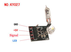
| + | This module has two parts - an LED and a mercury tilt switch. Pins are 1 G (ground), 2 + (5V power), 3 S signal and 4 L (LED.) | ||
| + | If you wired up 1 & 2 to power, pin 3 (signal) will alternate between 5V (HIGH) and 0V (LOW) as you tilt the module. If you connect a current limiting resistor to L2, you can use it as a blinking LED. | ||
*[https://s3.amazonaws.com/linksprite/Arduino_kits/advanced_sensors_kit/KY027+code.pdf Arduino Sample Code] | *[https://s3.amazonaws.com/linksprite/Arduino_kits/advanced_sensors_kit/KY027+code.pdf Arduino Sample Code] | ||
|- | |- | ||
| Line 170: | Line 218: | ||
| [[File:ky028.jpg | 300px]] | | [[File:ky028.jpg | 300px]] | ||
| | | | ||
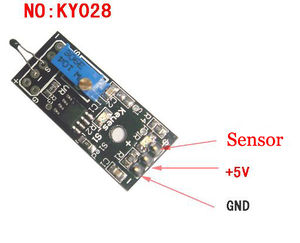
| + | Digital temperature module and a digital interface, built-in 13 LED build a simple circuit, making the temperature warning lamp 13 comes with digital interfaces of the LED, the digital temperature sensor connected digital three interfaces, when the digital temperature sensor senses a key signal, LED lights, otherwise off. | ||
*[https://s3.amazonaws.com/linksprite/Arduino_kits/advanced_sensors_kit/KY020+code.pdf Arduino Sample Code] | *[https://s3.amazonaws.com/linksprite/Arduino_kits/advanced_sensors_kit/KY020+code.pdf Arduino Sample Code] | ||
|- | |- | ||
| Line 176: | Line 225: | ||
| [[File:ky031.jpg | 300px]] | | [[File:ky031.jpg | 300px]] | ||
| | | | ||
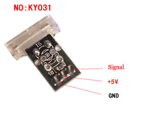
| + | Knock sensor module and a digital interface, built-in LED build a simple circuit to produce | ||
| + | percussion flasher. | ||
| + | Interface comes with digital LED, will knock sensor connected digital 3 interface, when | ||
| + | percussion sensor senses measure to percussive signals, LED flashing light. | ||
*[https://s3.amazonaws.com/linksprite/Arduino_kits/advanced_sensors_kit/KY031+code.pdf Arduino Sample Code] | *[https://s3.amazonaws.com/linksprite/Arduino_kits/advanced_sensors_kit/KY031+code.pdf Arduino Sample Code] | ||
|- | |- | ||
| Line 182: | Line 235: | ||
|[[File:ky032.jpg | 300px]] | |[[File:ky032.jpg | 300px]] | ||
| | | | ||
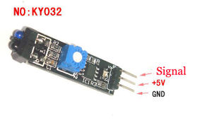
| + | Obstacle avoidance sensor module KY-032 for Arduino: | ||
| + | With 4 pins, use an infrared beam to detect proximity of obstacles. | ||
| + | The potentiometers can be used to adjust sensitivity. | ||
| + | Pin 1 is Ground, pin 2 is 5V power, pin 3 is digital output (on/off depending on the beam), 4 is enabling. | ||
*[https://s3.amazonaws.com/linksprite/Arduino_kits/advanced_sensors_kit/KY031+code.pdf Arduino Sample Code] | *[https://s3.amazonaws.com/linksprite/Arduino_kits/advanced_sensors_kit/KY031+code.pdf Arduino Sample Code] | ||
|- | |- | ||
| Line 194: | Line 251: | ||
| [[File:ky034.jpg | 300px]] | | [[File:ky034.jpg | 300px]] | ||
| | | | ||
| + | Automatic flashing colorful LED module KY-034 for Arduino: | ||
| + | *7 color flashing LED module automatically uses 5mm round high-brightness light-emitting diode which has the following characteristics: | ||
| + | *Shape: Round LED 5mm DIP type | ||
| + | *Working voltage: DC 3.0V - 4.5V | ||
| + | |||
*[https://s3.amazonaws.com/linksprite/Arduino_kits/advanced_sensors_kit/KY034+code.pdf Arduino Sample Code] | *[https://s3.amazonaws.com/linksprite/Arduino_kits/advanced_sensors_kit/KY034+code.pdf Arduino Sample Code] | ||
|- | |- | ||
| Line 200: | Line 262: | ||
| [[File:ky035.jpg | 300px]] | | [[File:ky035.jpg | 300px]] | ||
| | | | ||
| + | Analog magnetic sensor module and a digital interface, built-in 13 LED build a simple circuit to produce a magnetic flash | ||
| + | Makers.13 comes with digital interfaces of the LED, the analog magnetic sensor connected to the power board analog 5 ARDUINO Interfaces, when analog magnetic sensor to a signal, LED lights,otherwise the lights out. | ||
*[https://s3.amazonaws.com/linksprite/Arduino_kits/advanced_sensors_kit/KY031+code.pdf Arduino Sample Code] | *[https://s3.amazonaws.com/linksprite/Arduino_kits/advanced_sensors_kit/KY031+code.pdf Arduino Sample Code] | ||
|- | |- | ||
| Line 212: | Line 276: | ||
| [[File:ky037.jpg | 300px]] | | [[File:ky037.jpg | 300px]] | ||
| | | | ||
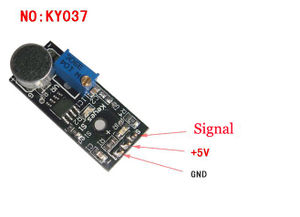
| + | For sound detection module has two outputs: | ||
| + | *AO, analog output, real-time output voltage signal of the microphone | ||
| + | *DO, when the sound intensity reaches a certain threshold, the output high and low signal | ||
| + | |||
| + | Module features: | ||
| + | *There is a mounting screw hole 3mm | ||
| + | *Use 5v DC power supply | ||
| + | *with analog output | ||
| + | *there are threshold level output flip | ||
| + | *high sensitive microphone and high sensitivity. | ||
| + | *a power indicator light | ||
| + | *the comparator output is light | ||
*[https://s3.amazonaws.com/linksprite/Arduino_kits/advanced_sensors_kit/KY031+code.pdf Arduino Sample Code] | *[https://s3.amazonaws.com/linksprite/Arduino_kits/advanced_sensors_kit/KY031+code.pdf Arduino Sample Code] | ||
|- | |- | ||
| KY038: | | KY038: | ||
Microphone Module | Microphone Module | ||
| − | | [[File: | + | | [[File:KY038.png| 300px]] |
| | | | ||
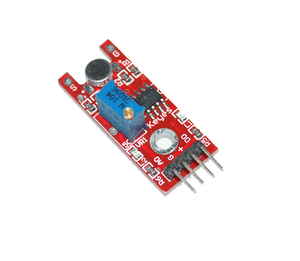
| + | Microphone sound sensor module KY-038 for Arduino: | ||
| + | *LM393 main chip | ||
| + | *Electric condenser microphone | ||
| + | *Features Single channel signal output | ||
| + | *Low level output signal used for sound control light | ||
| + | *Great module for sound alarm system | ||
| + | *Working voltage: DC 4-6V | ||
| + | *Interface definition: | ||
| + | **AO: analog output sensor | ||
| + | **GND: ground | ||
| + | **VCC: Power supply input range: 3V-24V. | ||
| + | **DO: Digital Output (comparator output) | ||
| + | *Two red LED indication: POWER and SENSOR. POWER: Power is off. SENSOR: When the microphone senses sound reaches a certain value, this LED light. | ||
*[https://s3.amazonaws.com/linksprite/Arduino_kits/advanced_sensors_kit/KY031+code.pdf Arduino Sample Code] | *[https://s3.amazonaws.com/linksprite/Arduino_kits/advanced_sensors_kit/KY031+code.pdf Arduino Sample Code] | ||
|- | |- | ||
| Line 224: | Line 313: | ||
| [[File:ky039.jpg | 300px]] | | [[File:ky039.jpg | 300px]] | ||
| | | | ||
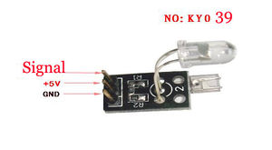
| + | This project uses bright infrared (IR) LED and a phototransistor to detect the pulse of the finger, a red LED flashes with each pulse. | ||
| + | Pulse monitor works as follows: The LED is the light side of the finger, and phototransistor on the other side of the finger, phototransistor used to obtain the flux emitted, when the blood pressure pulse by the finger when the resistance of the phototransistor will be slight changed. | ||
| + | |||
| + | We chose a very high resistance resistor R1, because most of the light through the finger is absorbed,it is desirable phototransistor sensitive enough.Resistance can be selected by experiment to get the best results. | ||
| + | The most important is to keep the shield stray light into the phototransistor. For home lighting that is particularly important because the lights at home mostly based 50HZ or 60HZ fluctuate, so faint heartbeat will add considerable noise. | ||
*[https://s3.amazonaws.com/linksprite/Arduino_kits/advanced_sensors_kit/KY039+code.pdf Arduino Sample Code] | *[https://s3.amazonaws.com/linksprite/Arduino_kits/advanced_sensors_kit/KY039+code.pdf Arduino Sample Code] | ||
|- | |- | ||
| KY040: | | KY040: | ||
Rotation Encoder Module | Rotation Encoder Module | ||
| − | |[[File: | + | |[[File:KY040.png| 300px]] |
| | | | ||
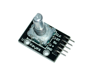
| + | By rotating the rotary encoder can be counted in the positive direction and the reverse direction during rotation of the output pulse frequency, unlike rotary potentiometer counter, which species rotation counts are not limited. With the buttons on the rotary encoder can be reset to its initial state, that starts counting from 0. | ||
| + | |||
| + | How it works: incremental encoder is a displacement of the rotary pulse signal is converted to a series of digital rotary sensors. These pulses are used to control angular displacement. In Eltra angular displacement encoder conversion using a photoelectric scanning principle. Reading system of alternating light transmitting window and the window is not consisting of radial indexing plate (code wheel) rotating basis, while being an infrared light source vertical irradiation light to the code disk image onto the receiving on the surface. Receiver is covered with a diffraction grating, which has the same code disk window width. The receiver's job is to feel the rotation of the disc resulting changes, and change the light into corresponding electrical changes. Then the low-level signals up to a higher level, and generates no interference square pulse, which must be processed by electronic circuits. Reading systems typically employ a differential manner, about the same but the phase difference of the two waveforms different by 180°compared to the signal in order to improve the quality and stability of the output signal. Reading is then the difference between the two signals formed on the basis,thus eliminating the interference. | ||
*[https://s3.amazonaws.com/linksprite/Arduino_kits/advanced_sensors_kit/KY040+code.pdf Arduino Sample Code] | *[https://s3.amazonaws.com/linksprite/Arduino_kits/advanced_sensors_kit/KY040+code.pdf Arduino Sample Code] | ||
|} | |} | ||
Latest revision as of 22:42, 9 July 2014
| Item | Picture | Description |
|---|---|---|
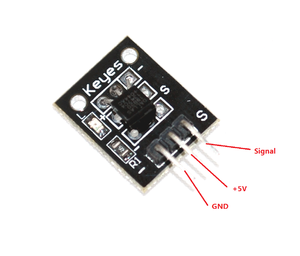
| KY001:
Temperature Sensor Module |
|
This module measures the temperature and reports it through the 1-wire bus digitally to the Arduino. |
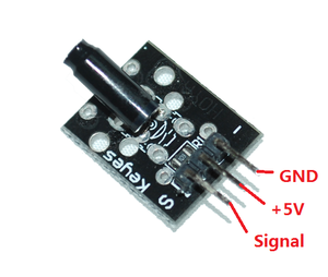
| KY002:
Shock Sensor Module |
|
This module is digital shock sensor. It will output a high level signal when it detects a shock event. |
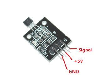
| KY003:
Hall Magnetic Field Sensor Module |
|
This module can be used to detect the presence of an magnetic field. If there is an magnetic field present, it will report a high level signal. |
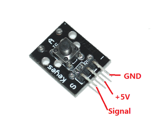
| KY004:
Momentary Button Module |
|
This is a button module. When the button is pressed, it will a high level signal. |
| KY005:
Infrared Transmitter Module |
|
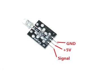
This is an infrared transmitter module that is used to emit infrared signal. |
| KY006:
Buzzer Module |
|
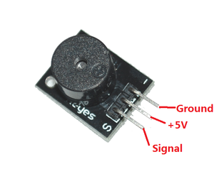
This is an active buzzer module that can make different sound. |
| KY008:
Laser Diode Module |
|
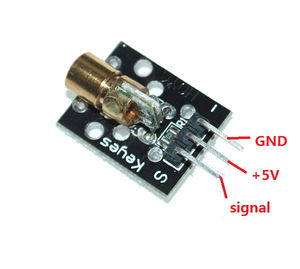
This is a laser emitter diode. The working voltage is 5V, with a wavelength of 650nm. |
| KY009:
RGB three colors LEDs module |
|
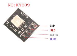
This is a surface mount three-color LED module that can make any color we want by combing different intensities of Red, Blue and Green. |
| KY010:
Light Block Sensor Module |
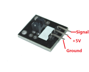
|
This is a light block sensor module, where there is an object in the middle of the U shape. The sensor will output a high level signal. |
| KY011:
Dual Light LEDs module |
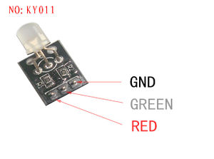
|
This is a dual color LED module. |
| KY012:
Buzzer Module |
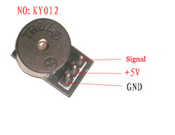
|
This is a nonactive buzzer module. |
| KY013:
Analog Temperature Sensor |
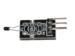
|
This is an analog temperature sensor that outputs it voltage in proportional to the temperature. |
| KY015:
Temprature and Humidity Sensor |
|
This DHT11 Temperature and Humidity Sensor features a calibrated digital signal output with the temperature and humidity sensor complex,ensureing the high reliability and excellent long-term stability. A high-performance 8-bit microcontroller is connected. This sensor includes a resistive element and a sense of wet NTC temperature measuring devices. It has excellent quality, fast response, anti-interference ability and high cost performance advantages. |
| KY016:
RGB three colors LED module |
|
This is a through the hole three-color LED module that can make any color we want by combing different intensities of Red, Blue and Green. |
| KY017:
Quicksilver Switch Module |
|
A tilt switch that can turn on and off depending on the tilt position. The switch is mercury. |
| KY018:
Optosensor Module |
|
Photoresistors are semiconductor photosensitive devices, in addition to having high sensitivity, fast response, consistent with the spectral characteristics and value of good features Under a high temperature, and humidity in harsh environments, it also can maintain a high degree of stability and reliability Wide pan used cameras, solar garden lights, lawn, detectors, clock, music, cups, gift boxes, mini-night light, light voice switches, lights automatically switch toys and a variety of light control, light control lighting, lamps and other light automatic opening control field |
| KY019:
5V DC Relay Module |
|
This is 1 channel relay module with the following spec:
|
| KY020:
Tilt Switch Module |
|
Tilt switch module and a digital interface, built-in 13 LED build a simple circuit to produce tilt warning lamp 13 comes with digital interfaces of the LED, the tilt switch sensor interface to access digital 3,when the tilt open Off sensor senses a key signal, LED lights, otherwise off. |
| KY021:
Mini Reed Switch Module |
|
Reed module and the interface comes with digital 13 LED build a simple circuit to produce a Reed warning lamp 13 comes with digital interfaces of the LED, the Reed sensor access number 3 interface, when Reed sensors Sensed a key signal, LED lights, otherwise off. |
| KY022:
Infrared Receiver Module |
|
This is the infrared receiver module, with the following features:
|
| KY023:
Mini Dual Axis JoyStick |
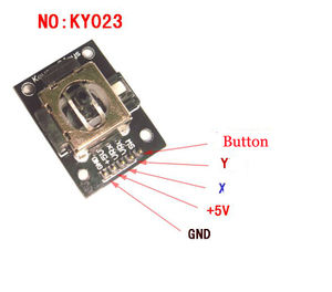
|
On the principle, the control rod can be considered that it is organized by the two potentiometer and a button.When using, it can connect with Arduino sensor shield,and connect Arduino corresponding pins through Arduino sensor cables. It as the following spec:
|
| KY024:
Linear magnetic Hall sensor |
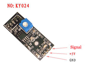
|
Linear Hall magnetic module and a digital interface, built-in 13 LED build a simple circuit to produce a magnetic field warning lamp 13 comes with digital interfaces of the LED, the linear Hall sensor magnetometer access number 3 interface, when linear Hall magnetometer Sensor senses a key signal, LED lights, otherwise off. |
| KY025:
Big Reed Switch Module |
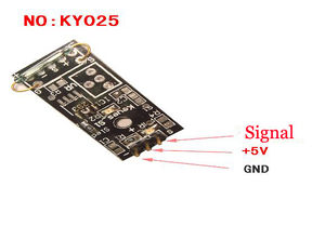
|
Reed module and the interface comes with digital 13 LED build a simple circuit to produce a Reed warning lamp 13 comes with digital interfaces of the LED, the Reed sensor access number 3 interface, when Reed sensors Sensed a key signal, LED lights, otherwise off. |
| KY026:
Flame Sensor Module |
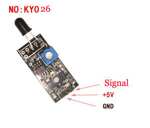
|
Sensor for flame wavelengths between 760 nm to 1100 nm infrared is most sensitive
|
| KY027:
Magic LED cup Module |
|
This module has two parts - an LED and a mercury tilt switch. Pins are 1 G (ground), 2 + (5V power), 3 S signal and 4 L (LED.) If you wired up 1 & 2 to power, pin 3 (signal) will alternate between 5V (HIGH) and 0V (LOW) as you tilt the module. If you connect a current limiting resistor to L2, you can use it as a blinking LED. |
| KY028:
Digital Temprateure Sensor Module |
|
Digital temperature module and a digital interface, built-in 13 LED build a simple circuit, making the temperature warning lamp 13 comes with digital interfaces of the LED, the digital temperature sensor connected digital three interfaces, when the digital temperature sensor senses a key signal, LED lights, otherwise off. |
| KY031:
Shock Sensor Module |
|
Knock sensor module and a digital interface, built-in LED build a simple circuit to produce percussion flasher. Interface comes with digital LED, will knock sensor connected digital 3 interface, when percussion sensor senses measure to percussive signals, LED flashing light. |
| KY032:
Obstacle Sensor Module |
|
Obstacle avoidance sensor module KY-032 for Arduino: With 4 pins, use an infrared beam to detect proximity of obstacles. The potentiometers can be used to adjust sensitivity. Pin 1 is Ground, pin 2 is 5V power, pin 3 is digital output (on/off depending on the beam), 4 is enabling. |
| KY033:
Line follow Sensor Module |
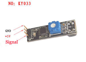
|
|
| KY034:
7 Colors LED Blinking Module |
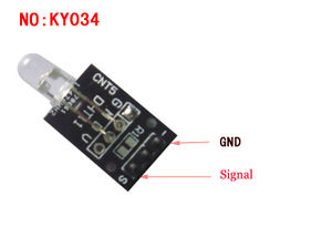
|
Automatic flashing colorful LED module KY-034 for Arduino:
|
| KY035:
Hall Sensor Module |
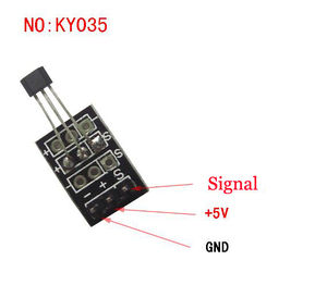
|
Analog magnetic sensor module and a digital interface, built-in 13 LED build a simple circuit to produce a magnetic flash Makers.13 comes with digital interfaces of the LED, the analog magnetic sensor connected to the power board analog 5 ARDUINO Interfaces, when analog magnetic sensor to a signal, LED lights,otherwise the lights out. |
| KY036:
Metal Touch Sensor Module |
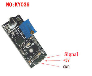
|
|
| KY037:
High Sensitive Microphone Module |
|
For sound detection module has two outputs:
Module features:
|
| KY038:
Microphone Module |
|
Microphone sound sensor module KY-038 for Arduino:
|
| KY039:
Heatbeat Sensor Module |
|
This project uses bright infrared (IR) LED and a phototransistor to detect the pulse of the finger, a red LED flashes with each pulse. Pulse monitor works as follows: The LED is the light side of the finger, and phototransistor on the other side of the finger, phototransistor used to obtain the flux emitted, when the blood pressure pulse by the finger when the resistance of the phototransistor will be slight changed. We chose a very high resistance resistor R1, because most of the light through the finger is absorbed,it is desirable phototransistor sensitive enough.Resistance can be selected by experiment to get the best results. The most important is to keep the shield stray light into the phototransistor. For home lighting that is particularly important because the lights at home mostly based 50HZ or 60HZ fluctuate, so faint heartbeat will add considerable noise. |
| KY040:
Rotation Encoder Module |
|
By rotating the rotary encoder can be counted in the positive direction and the reverse direction during rotation of the output pulse frequency, unlike rotary potentiometer counter, which species rotation counts are not limited. With the buttons on the rotary encoder can be reset to its initial state, that starts counting from 0. How it works: incremental encoder is a displacement of the rotary pulse signal is converted to a series of digital rotary sensors. These pulses are used to control angular displacement. In Eltra angular displacement encoder conversion using a photoelectric scanning principle. Reading system of alternating light transmitting window and the window is not consisting of radial indexing plate (code wheel) rotating basis, while being an infrared light source vertical irradiation light to the code disk image onto the receiving on the surface. Receiver is covered with a diffraction grating, which has the same code disk window width. The receiver's job is to feel the rotation of the disc resulting changes, and change the light into corresponding electrical changes. Then the low-level signals up to a higher level, and generates no interference square pulse, which must be processed by electronic circuits. Reading systems typically employ a differential manner, about the same but the phase difference of the two waveforms different by 180°compared to the signal in order to improve the quality and stability of the output signal. Reading is then the difference between the two signals formed on the basis,thus eliminating the interference. |