Difference between revisions of "DC 5V Eight Channels Relay Breakout with Optoisolator"
(→Description) |
(→Description) |
||
| Line 1: | Line 1: | ||
== Description == | == Description == | ||
| − | |||
[[File:1-146.jpg]] | [[File:1-146.jpg]] | ||
| + | |||
| + | [[File:1-147.jpg]] | ||
A breakout board with 8 channel 5V DC relay. The control signal is DC 5V - 7.5V. It can control 10A 250VAC, 10A 30VDC load. | A breakout board with 8 channel 5V DC relay. The control signal is DC 5V - 7.5V. It can control 10A 250VAC, 10A 30VDC load. | ||
Latest revision as of 03:17, 29 March 2016
Description
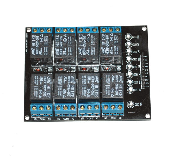
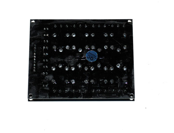
A breakout board with 8 channel 5V DC relay. The control signal is DC 5V - 7.5V. It can control 10A 250VAC, 10A 30VDC load.
Size: 70mm X 17mm X 20mm.
The major component is EL817 and SRD-DV5V-SL-C.
Features
- Outputs have LED indicators.
- The input can be directly controlled by MCU's IOs.
- With optoisolators installed.
- Use diode to protect
- Response time < 20ms
- Relay can operate more than 100 thousands times.
- Four channels can be controlled at the as time.
- Independent input/output power supplies.
Interface Definitions
Input:
- GND -- Negative Power Supply of Optoisolator control
- VCC -- Positive Power Supply of Optoisolator Control
- IN1 -- Control Signal No. 1 (Active Low, activate the relay)
- IN2 -- Control Signal No. 2 (Active Low, activate the relay)
- IN3 -- Control Signal No. 3 (Active Low, activate the relay)
- IN4 -- Control Signal No. 4 (Active Low, activate the relay)
- IN5 -- Control Signal No. 4 (Active Low, activate the relay)
- IN6 -- Control Signal No. 4 (Active Low, activate the relay)
- IN7 -- Control Signal No. 4 (Active Low, activate the relay)
- IN8 -- Control Signal No. 4 (Active Low, activate the relay)
- V- -- Negative Power Supply of Relay
- V+ -- Positive Power Supply of Relay

