Difference between revisions of "Tilt Sensor"
Katherine.d (talk | contribs) (→Schematic) |
Yajuan.dai (talk | contribs) (→Adjustable coupling) |
||
| (8 intermediate revisions by 2 users not shown) | |||
| Line 1: | Line 1: | ||
== Overview == | == Overview == | ||
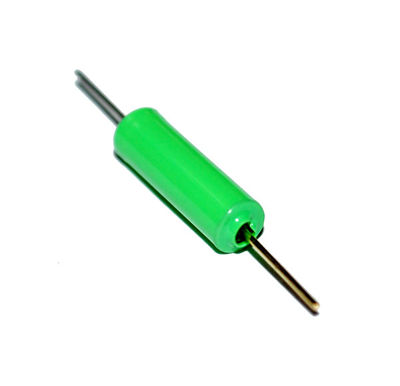
| − | + | A tilt sensor is a simplified accelerometer. It is a switch that can detect basic motion/orientation. The metal tube has a little metal ball that rolls around in it. When it is tilted upright, the ball rolls onto the contacts sticking out of end and shorts them together. | |
| − | + | Shown in Figure 6.1 is the tile sensor SW-460D. The electric characteristics of this sensor are listed in Table 6.1. The minimum tilt angel of this sensor is 2-5°. | |
| − | + | [[File:tilt sensor.jpg | 400px]] | |
| − | === | + | ===Adjustable coupling=== |
| − | + | **[http://linksprite.com/wiki/index.php5?title=Sensors_Pack_for_Arduino Sensors Pack for Arduino] [KIT_SENPACK] | |
| − | |||
| − | |||
| − | |||
| − | === | + | == Specifications == |
| − | |||
| − | |||
| − | |||
| − | |||
| − | |||
| − | |||
| − | |||
| − | |||
| − | |||
| − | |||
| − | |||
| − | |||
| − | |||
| − | |||
| − | |||
| − | |||
| − | |||
| − | |||
| − | |||
| − | |||
=== Characteristics === | === Characteristics === | ||
{| class="wikitable" border="1" | {| class="wikitable" border="1" | ||
| − | |+align="center" |Electrical Characteristics | + | |+align="center" |SW-460D Electrical Characteristics |
|- | |- | ||
| − | ! align="center" style="width: | + | ! align="center" style="width:150px" |Voltage |
| − | + | ! align="center" style="width:150px" |Current | |
| − | ! align="center" style="width: | ||
! align="center" style="width:200px" |Conduction Time | ! align="center" style="width:200px" |Conduction Time | ||
! align="center" style="width:200px" |Path Resistance | ! align="center" style="width:200px" |Path Resistance | ||
| Line 48: | Line 24: | ||
! align="center" style="width:200px" |Resistance To Temperature | ! align="center" style="width:200px" |Resistance To Temperature | ||
|- | |- | ||
| − | | align="center" style="width: | + | | align="center" style="width:150px" |12V |
| − | + | | align="center" style="width:150px" |5mA | |
| − | | align="center" style="width: | ||
| align="center" style="width:200px" |20mS | | align="center" style="width:200px" |20mS | ||
| align="center" style="width:200px" |>10M omh | | align="center" style="width:200px" |>10M omh | ||
| Line 61: | Line 36: | ||
[[File:schematic of tilt.jpg | 400px]] | [[File:schematic of tilt.jpg | 400px]] | ||
| − | == Programming == | + | == Example Project == |
| + | |||
| + | ===Hardware Preparation === | ||
| + | |||
| + | The following hardware is needed in this project. | ||
| + | |||
| + | :*An Arduino Duemilanove board or compatible Arduino controller | ||
| + | :*1 tilt sensor | ||
| + | :*1 Prototyping Shield | ||
| + | :*1 mini breadboard | ||
| + | :*A 4-pin pitch pin header | ||
| + | :*A resistor and a capacitor | ||
| + | :*A few jumper wires | ||
| + | |||
| + | === Programming === | ||
The program below uses the tilt sensor to control the LED. | The program below uses the tilt sensor to control the LED. | ||
Latest revision as of 10:04, 19 August 2014
Contents
Overview
A tilt sensor is a simplified accelerometer. It is a switch that can detect basic motion/orientation. The metal tube has a little metal ball that rolls around in it. When it is tilted upright, the ball rolls onto the contacts sticking out of end and shorts them together.
Shown in Figure 6.1 is the tile sensor SW-460D. The electric characteristics of this sensor are listed in Table 6.1. The minimum tilt angel of this sensor is 2-5°.
Adjustable coupling
- Sensors Pack for Arduino [KIT_SENPACK]
Specifications
Characteristics
| Voltage | Current | Conduction Time | Path Resistance | Open Circuit Resistance | Resistance To Temperature |
|---|---|---|---|---|---|
| 12V | 5mA | 20mS | >10M omh | 10M omh | 100°C |
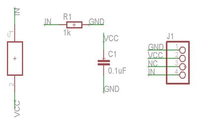
Schematic
Example Project
Hardware Preparation
The following hardware is needed in this project.
- An Arduino Duemilanove board or compatible Arduino controller
- 1 tilt sensor
- 1 Prototyping Shield
- 1 mini breadboard
- A 4-pin pitch pin header
- A resistor and a capacitor
- A few jumper wires
Programming
The program below uses the tilt sensor to control the LED.
Sample code:
<syntaxhighlight lang="c">
int ledPin = 13; // Connect LED to pin 13 int switcher = 3; // Connect Tilt sensor to Pin3
void setup() {
 pinMode(ledPin, OUTPUT);      // Set digital pin 13 to output mode
 pinMode(switcher, INPUT);       // Set digital pin 3 to input mode
} void loop() {
  if(digitalRead(switcher)==HIGH) //Read sensor value
    {
       digitalWrite(ledPin, HIGH);   // Turn on LED when the sensor is tilted
    }
  else
    {
       digitalWrite(ledPin, LOW);    // Turn off LED when the sensor is not triggered
    }
}
</syntaxhighlight>

