Difference between revisions of "Rover: WiFi Video Streaming Robot"
(→Hardware Installation) |
(→Usage) |
||
| Line 74: | Line 74: | ||
We didn't provide sample of how to use the ultrasonic sensor breakout included on the Rover kit. However, the user can find the information at [http://linksprite.com/wiki/index.php5?title=Ultrasonic_Range_Sensor here]. | We didn't provide sample of how to use the ultrasonic sensor breakout included on the Rover kit. However, the user can find the information at [http://linksprite.com/wiki/index.php5?title=Ultrasonic_Range_Sensor here]. | ||
| + | |||
| + | '''Mechanical Assembly Steps''' | ||
| + | |||
| + | |||
| + | [[File:Assemblystep 1.jpg]] | ||
| + | |||
| + | [[File:Assemblystep 2.jpg]] | ||
| + | |||
| + | [[File:Assemblystep 3.jpg]] | ||
| + | |||
| + | [[File:Assemblystep 4.jpg]] | ||
| + | |||
| + | [[File:Assemblystep 5.jpg]] | ||
| + | |||
| + | [[File:Assemblystep 6.jpg]] | ||
| + | |||
| + | [[File:Assemblystep 7.jpg]] | ||
| + | |||
| + | [[File:Assemblystep 8.jpg]] | ||
| + | |||
| + | [[File:Assemblystep 9.jpg]] | ||
| + | |||
| + | [[File:Assemblystep 10.jpg]] | ||
| + | |||
| + | [[File:Assemblystep 11.jpg]] | ||
| + | |||
=== Programming === | === Programming === | ||
Revision as of 19:16, 24 January 2013
Contents
[hide]Introduction
Features
Application Ideas
Cautions
Schematic
Specification
Pin definition and Rating
Mechanic Dimensions
Usage
Hardware Installation
Control Board:
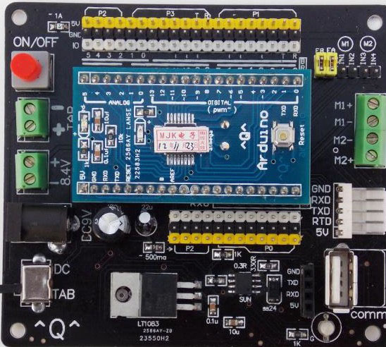
The Arduino control board on the Rover is "Arduino Diecimila or Duemilanove W/Atmea168", when you use Arduino IDE to select the board type.
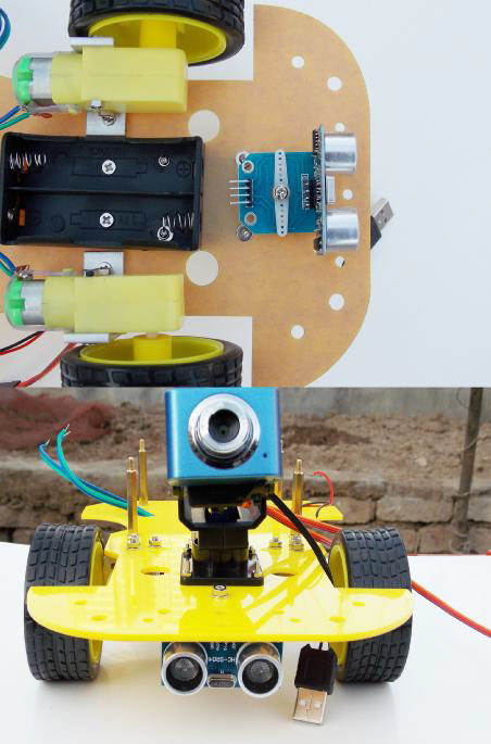
Camera/Servo:
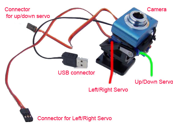
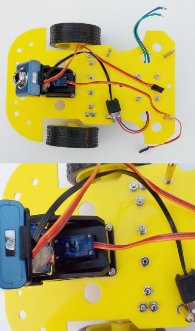
The servo platform has two part: up/down and left/right. Both directions can do 180 degree rotation. The USB camera is plugged into the WiFi module. Up/down servo connector is connected to pin 11 of the control board, and left/right servo connector is connected to pin 10 of the control board.
Ultrasonic Sensor:
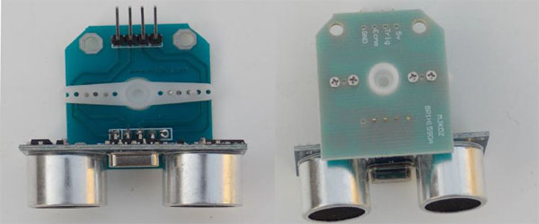
The ultrasonic sensor is used to detect object and avoid collision. This sensor has 4 pins: 5V is connected to 5V pin of the control board; Trig is connected to pin 9 of the control board; Echo is connected to pin 9 of the control board. GND is connected to GND of the control board.
We didn't provide sample of how to use the ultrasonic sensor breakout included on the Rover kit. However, the user can find the information at here.
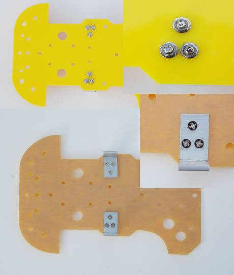
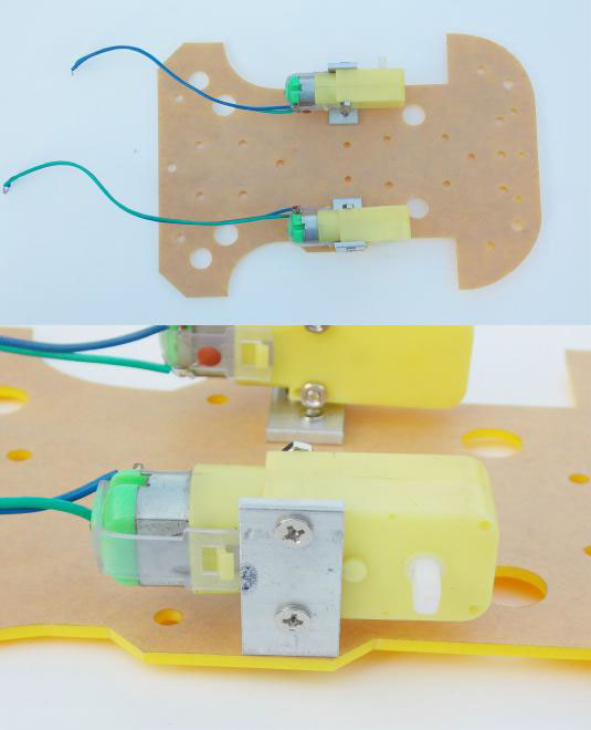
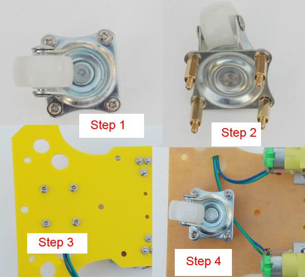
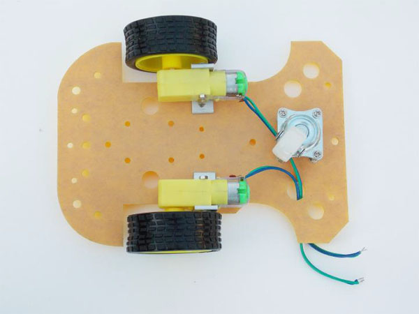
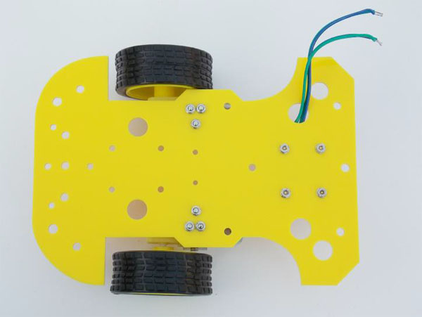
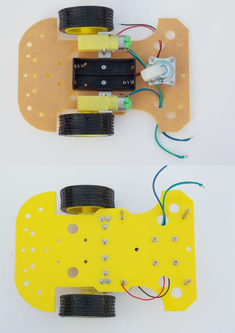
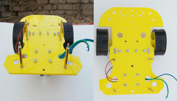
Mechanical Assembly Steps
Programming
The Arduino control board on the Rover is "Arduino Diecimila or Duemilanove W/Atmea168".
FAQ
Please list your question here:
Support
If you have questions or other better design ideas, you can go to our forum to discuss or creat a ticket for your issue at linksprite support.
Resources
How to buy
See Also
Other related products and resources.
Licensing
This documentation is licensed under the Creative Commons Attribution-ShareAlike License 3.0 Source code and libraries are licensed under GPL/LGPL, see source code files for details.
