Difference between revisions of "Quad-band GPRS/GSM Shield for Arduino"
Katherine.d (talk | contribs) (→Introduction) |
(→Hardware Installation) |
||
| Line 56: | Line 56: | ||
| − | + | J1 and J2 are used to choose how RX/TX of SM5100B is going to connected to Arduino. | |
| − | + | RX/TX is the RX/TX of SM5100B module. | |
| + | MTX/MRX is the TX/RX of Atmega328. | ||
| + | D3 and D2 are the I/O of Atmega328 if soft serial is used. | ||
=== Programming === | === Programming === | ||
Revision as of 13:39, 7 December 2012
Contents
Introduction
Model:Arduino_SM5100_1
Features
Application Ideas
Cautions
Schematic
Specification
Pin definition and Rating
Mechanic Dimensions
Usage
Hardware Installation
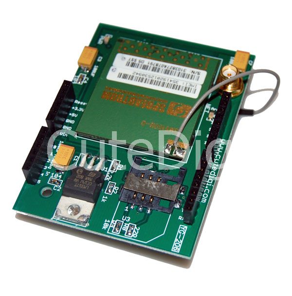
J1 and J2 are used to choose how RX/TX of SM5100B is going to connected to Arduino. RX/TX is the RX/TX of SM5100B module. MTX/MRX is the TX/RX of Atmega328. D3 and D2 are the I/O of Atmega328 if soft serial is used.
Programming
FAQ
Please list your question here:
Support
If you have questions or other better design ideas, you can go to our forum to discuss or creat a ticket for your issue at linksprite support.
Resources
How to buy
See Also
Other related products and resources.
Licensing
This documentation is licensed under the Creative Commons Attribution-ShareAlike License 3.0 Source code and libraries are licensed under GPL/LGPL, see source code files for details.
