Difference between revisions of "ONetSwitch30"
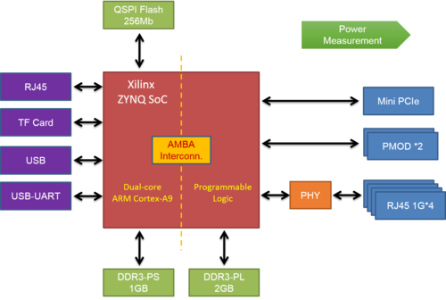
(→Block Diagram) |
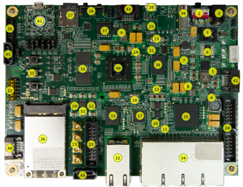
(→Board Layout) |
||
| Line 41: | Line 41: | ||
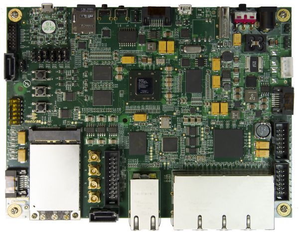
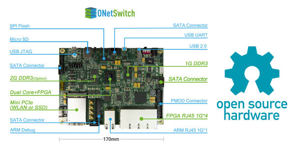
== Board Layout == | == Board Layout == | ||
| − | [[File:1-83.png]] | + | [[File:1-83.png|500px]] |
| − | [[File:1-84.png]] | + | [[File:1-84.png|500px]] |
== Specification == | == Specification == | ||
Revision as of 05:20, 2 February 2016
ONetSwitch30
Overview
ONetSwitch30 is an All Programmable open networking innovation platform.
ONetSwitch30 is based on the Xilinx Zynq-7000 SoC, and mainly adopts the Gigabit ports. It can achieve a comprehensive experiment platform integrating calculations, storage, networks and interconnection by extension. Both its software and hardware can realize custom programming. Its reference designs are abundant and flexible, can be used to various researches on the evolution of network prototypes, and the development of customized network products. Especially, the features of the miniaturization and low power are adapted to the multi-node network tests and deployments.
Features
- General
- Main Silicon XC7Z030-2SBG485
- Power Supply DC 12V
- Primary Config. TF card
- Auxiliary Config. QSPI flash/JTAG
- Processing System
- Processor _Dual ARM Cortex-A9@800MHz_
- Cache (L1)32KB Inst. + 32KB Data per core; (L2)512KB; (OCM)256KB
- DRAM DDR3 1GBytes
- Flash Quad SPI flash 256Mb
- DMA 8 channel (4 for Programmable Logic)
- Ethernet 1x GE RJ45
- Peripherals USB / USB-UART / USB JTAG / TF card
- Programmable Logic
- FPGA Logic 125K LCs, Kintex-7, ~1.9M ASIC gates
- Host I/F AMBA AXI4 interconnect, max 100Gbps between PS-PL
- DRAM DDR3 2GBytes
- Ethernet 4x GE RJ45
- Peripherals 2x PMOD
- User IO user LEDs/push buttons/DIP switch
- Extension mini PCIe for wireless NIC or SSD
Block Diagram
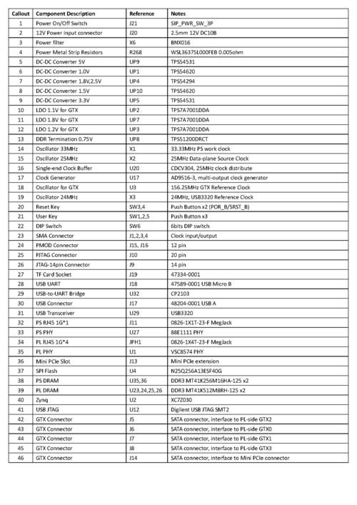
Board Layout
Specification
For details of the board hardware, please download the ONetSwitch30 Hardware User Guide.
workflow
Overview
A bottom-up approach is recommended when developing on the Xilinx Zynq SoC-based ONetSwitch.
The figure below from Xilinx Wiki shows a high level block diagram of the Xilinx design flow for Zynq AP SoC.
[[File:1-87.png]
For any layer or component in this hierarchy, you can either download the pre-built images for quick use, or modify then generate it by yourself in the way described below.
Get Prepared
- Prepare the Boot Medium
Xilinx Zynq SoC offers different types for system booting, on your demand.
Here in the GitHub for an ONetSwitch, the SD boot is chosen as default. An FAT partition in the size of 512MB is used for storing the boot and kernel images, while an EXT partition typically larger than 1GB is for the root file system and the applications(e.g. OpenFlow switch software).
For the detailed how-to, please refer to Xilinx Wiki Prepare Boot Medium.
- Setup a Serial Console
It is a must to use the USB-UART when running an interactive program on the platform or debugging. Here's a helpful link on Xilinx Wiki Setup a Serial Console.
- Get a Linux Environment
Software development on ONetSwitch requires a Linux environment for easy cross compilation.
Ubuntu 12.04 LTS x86_64 may lack some needed 32-bit libraries. This can be fixed by installing ia32-libs.
Ubuntu 14.04 LTS x86_64 may also lack some needed 32-bit libraries. This can be fixed by installing libc6-i386.
- Install Xilinx Tools
Xilinx Vivado and SDK must be installed for ONetSwitch development. Download
Notice that, by 2014 Q4, all our projects are developed with Vivado 2013.4.
When working in a Linux environment, especially for software developers, remember to setup the environment variables for cross compiler and the Vivado/SDK tools.
<source lang="bash">export CROSS_COMPILE=arm-xilinx-linux-gnueabi- source <path-to-installation>/Vivado/<version>/settings32.sh # OR source <path-to-installation>/Vivado/<version>/settings64.sh</source>
Use Pre-Built Images
The pre-built images can be fetched mainly from
This repo stores the common FSBL, SSBL(u-boot), Linux kernel(uImage) and root file system(rootfs), as well as the SDN/OpenFlow executables. It is easy to find them in the repo according to the folder and file names.
The boot loaders are board-dedicated, while the kernel image and the rootfs are applicable to all ONetSwitch boards.
- ready-to-download
This is a sub-folder associated with each project, usually contains the FPGA image(system.bit) and the project-specific devicetree blob(devicetree.dtb).
The boot.bin, which is created by Xilinx SDK, always consists of the common FSBL and u-boot from common-bin above, and the project-specific system.bit.
An example here to prepare for an OpenFlow software switch (ofs-sw) on ONetSwitch30 using pre-built images.
You need to collect following items and make copies of them to the FAT partition.
| File | Repo | Link | | ---- | ---- | ---- | | boot.bin | onetswitch30 | ready-to-download/boot.bin |
| devicetree | onetswitch30 | ready-to-download/devicetree.dtb |
| kernel | common-bin | kernel/uImage |
You need also to extract the compressed rootfs to the EXT partition and then put the application images to somewhere in the extracted folder structure.
In this example, some runtime libs are required so the sw-lib is copied as well.
| File | Repo | Link | | ---- | ---- | ---- | | rootfs (EXT) | common-bin | rootfs/rootfs_ext4.tar.gz | | sw-lib | common-bin | lib/*| | sw-app | common-bin | ofs-sw/* |
Notice that, all the boot.bin are prepared to start the kernel in the EXT partition, using the pre-built u-boot with suffix -ext.elf in its file name. If you want to simply run all in an FAT partition, rootfs as uramdisk and the u-boot with suffix -ram.elf. The FPGA image should be used in the boot.bin regeneration.
| File | Repo | Link | | ---- | ---- | ---- | | system.bit | onetswitch30 | ready-to-download/res/onetswitch_top.bit | | fsbl | common-bin | fsbl/fsbl-ons30.elf | | u-boot (FAT) | common-bin | u-boot/u-boot-ons30-ram.elf | | u-boot (EXT) | common-bin | u-boot/u-boot-ons30-ext.elf | | rootfs (FAT) | common-bin | rootfs/uramdisk.image.gz |
Build the System
Zynq Hardware Design
The Zynq hardware design generates the system.bit, defining the ARM CPU settings in Zynq PS and the FPGA bitstream in Zynq PL.
- Create IP cores and hardware design * Configure the processor * Add and integrate IP cores * Generate the bitstream * Export the hardware design to SDK
The entire process is implemented in Xilinx Vivado tool. See more information in our Hardware Design Guide.
Zynq Software Design
The Zynq software design introduces several steps to build up an entire embedded system, from boot loader to Linux kernel, including * First stage boot loader, FSBL * Second stage boot loader, SSBL, using u-boot * Root file system, rootfs * Device tree * Linux kernel
The process needs Xilinx SDK, and working environment in Linux with cross compiler installed. See more information in our Software Design Guide.
Application Design
The applications, often the final target what we want, run on top of the OS (Linux as we mentioned above, or any others from 'bare-metal' to Android.)
For SDN/OpenFlow application, we have done following and hope to get more from you.
- A vSwitch running a CPqD ofsoftswitch13 ported to ARM ofs-sw
- An FPGA accelerated OFS, with both HW and SW flow tables ofs-hw
Integrate and Test
Prepare the Boot Image
The boot image, boot.bin, is created in Xilinx SDK, by assembling the FSBL, the FPGA image, and the SSBL in sequence.
1. Select 'Xilinx Tools' from the SDK menu
2. Choose 'Create Zynq Boot Image', a pop-up appears
3. Add fsbl.elf, system.bit, u-boot.elf sequentially
4. Click 'Create Image' and wait for the generation
5. Rename the output binary to boot.bin
Use the Test Sequence
Project-specific test sequence is provided as a demo. It mainly shows the usage of the board and the features of the application.
Try the test sequence and check the results.
Prepare Boot Medium
Input Files Required
Output Files Produced
- bootable SD card
Task Description
The following instructions are taken from the OMAPPedia wiki.
The following instructions assume a Linux system. Furthermore, most commands require root permissions. After completing this steps the SD card holds two partitions which can be read/written under Linux. Windows can - if at all - only access the FAT partition; but even this seems to depend on the card reader/driver used.
Insert SD card and figure out the corresponding device. The last lines of the dmesg output should tell you under which device file the inserted SD card is available in the system. dmesg
Warning: The following commands will use '/dev/sdX' to refer to the SD card device. Replace this with the actual device on your system. Executing the following commands on the wrong device may corrupt your data on other file systems. Also, all data on your SD card will be destroyed.
The fdisk utility does not seem to erase the first few bytes of the first sector in the card when the partition table is saved. Use dd to erase the first sector. dd if=/dev/zero of=/dev/sdX bs=1024 count=1
Calculate the new_cylinders value fdisk -l /dev/sdX
The output should look similar to this > Disk /dev/sdb: 8068 MB, 8068792320 bytes
249 heads, 62 sectors/track, 1020 cylinders, total 15759360 sectors
Units = sectors of 1 * 512 = 512 bytes
Sector size (logical/physical): 512 bytes / 512 bytes
I/O size (minimum/optimal): 512 bytes / 512 bytes
Disk identifier: 0x00000000
Disk /dev/sdb doesn't contain a valid partition table
Look for the size of the device in bytes and calculate the new number of cylinders using the following formula, dropping all fractions: > new_cylinders = <size> / 8225280
For the example output given above, we would write down new_cylinders = 8068792320 / 8225280 = 980.
Partition the SD card. We will create two partitions on the SD card. One 200 MB sized boot partition. And a second partition taking the remaining space on the SD card.
fdisk /dev/sdX
The dd command should have wiped all existing partition tables, if this is not the case, delete all existing partitions on the SD card. >Command (m for help):
Partition number (1-4): 1
Repeat this for all valid partitions numbers.
Now configure the sectors, heads and cylinders of the SD card.
Command (m for help): x
Expert command (m for help): h
Number of heads (1-256, default 30): 255
Expert command (m for help): s
Number of sectors (1-63, default 29): 63
Expert command (m for help): c
Number of cylinders (1-1048576, default 2286): <new_cylinders calculated from above>
Command (m for help): r
Now the actual partitions can be created
>Command (m for help): n
Partition type:
p primary (0 primary, 0 extended, 4 free)

e extended
Select (default p): p
Partition number (1-4, default 1): 1
First sector (2048-15759359, default 2048):
Using default value 2048
Last sector, +sectors or +size{K,M,G} (2048-15759359, default 15759359): +200M
Command (m for help): n
Partition type:
p primary (1 primary, 0 extended, 3 free)

e extended
Select (default p): p
Partition number (1-4, default 2): 2
First sector (411648-15759359, default 411648):
Using default value 411648
Last sector, +sectors or +size{K,M,G} (411648-15759359, default 15759359):
Using default value 15759359
Now, set the bootable flag and partition IDs >Command (m for help): a
Partition number (1-4): 1
Command (m for help): t
Partition number (1-4): 1
Hex code (type L to list codes): c
Changed system type of partition 1 to c (W95 FAT32 (LBA))
Command (m for help): t
Partition number (1-4): 2
Hex code (type L to list codes): 83
Check the new partition table and write the changes >Command (m for help): p
Disk /dev/sdb: 8068 MB, 8068792320 bytes
249 heads, 62 sectors/track, 1020 cylinders, total 15759360 sectors
Units = sectors of 1 * 512 = 512 bytes
Sector size (logical/physical): 512 bytes / 512 bytes
I/O size (minimum/optimal): 512 bytes / 512 bytes
Disk identifier: 0x920c958b
Device Boot Start End Blocks Id System
/dev/sdb1 * 2048 411647 204800 c W95 FAT32 (LBA)
/dev/sdb2 411648 15759359 7673856 83 Linux
Command (m for help): w
The partition table has been altered!
Calling ioctl() to re-read partition table.
WARNING: If you have created or modified any DOS 6.x
partitions, please see the fdisk manual page for additional
information.
Syncing disks.
Create file systems on the new partitions mkfs.vfat -F 32 -n boot /dev/sdX1 mkfs.ext4 -L root /dev/sdX2
Mount the boot partition mkdir -p /mnt/boot mount /dev/sdX1 /mnt/boot Copy the boot.bin or contents of the release archive to the SD card, e.g. cp boot.bin /mnt/boot/
Unmount the SD card umount /mnt/boot
The SD card can now be removed and transferred over to the target platform.
Ref:
Quick Start
Intro
An ONetSwitch enables users in different development roles to build a complete networking system in a single node. Users can build the embedded system either from scratch, or based on some pre-built images.
In either way, getting-started projects would help you * to get acquainted with the board and its components
- to make quick hardware tests on the main silicon and its peripherals
- to understand the usage and be ready for next-stage development
Project List
Project to verify the clocks, resets, memories, etc at the ARM CPU side.
Project to verify the rate and SI of the transceivers using PRBS generator.
Project to verify the PHYs and the MACs on each of the Ethernet ports.
Project to verify the Mini PCIe and the configuration of PCIe Root Complex.
Project to verify the calibration of PL QDRII+ SRAM, with traffic generator.
Project to verify the calibration and read/write operations on PL DDR3 SDRAM.
The table below shows the applicability.
