Difference between revisions of "Serial UART 16x2 LCD 3.3V"
(Created page with "= Introduction = The serial UART 16x2 LCD allows you to control a parallel based LCD over a single-wire serial interface. The serial LCD takes care of all the HD44780 commands...") |
(No difference)
|
Revision as of 01:59, 25 July 2016
Contents
Introduction
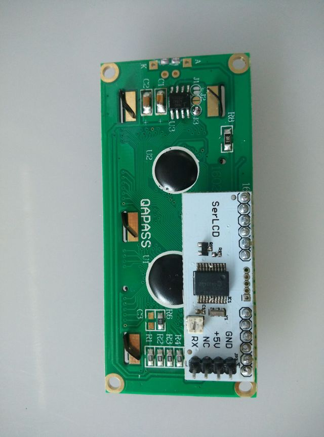
The serial UART 16x2 LCD allows you to control a parallel based LCD over a single-wire serial interface. The serial LCD takes care of all the HD44780 commands allowing seamless integration with any micro that can communicate over a wide range of TTL serial baud rates. The Communication with Serial 16x2 LCD requires 3.3V TTL serial at a default baud rate of 9600bps (8-N-1). You can adjust the baud to any standard rate between 2400 and 38400bps. The power, ground and RX pins are all broken out to a 4-pin 2.54mm pitch header. Serial 16x2 LCD has the ability to dim the backlight to conserve power if needed. There is also a potentiometer on the backpack to adjust the contrast.
Features
Embedded PIC 16F88 utilizes onboard UART for greater communication accuracy Baud rates of 9600 Greater processing speed at 10MHz Incoming buffer stores up to 80 characters Backlight transistor can handle up to 1A Pulse width modulation of backlight allows direct control of backlight brightness and current consumption All surface mount design allows a backpack that is half the size of the original Faster boot-up time Boot-up display can be turned on/off via firmware
Application Ideas
Cautions
Schematic
Specification
Item Min Typical Max Unit Voltage 4.3 4.6 3.3 V Current 53 84 128 mA Dimension 80.0×36.0×22.7 mm Net Weight 39 g
Pin definition and Rating
Mechanic Dimensions
Usage
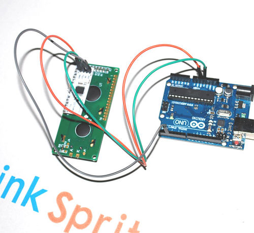
Hardware Installation
- Connect the 3.3V of Serial LCD to 3.3V on Arduino.
- Connect GND of Serial LCD to GND of Arduino.
- Connect RX of Serial LCD to digital 3 of Arduino.
Programming
The following is the sample code assuming that the RX of serial LCD is connected to digital 2 of Arduino. The following code has been tested on Arduino IDE 1.0.1.
- include <SoftwareSerial.h>
- define txPin 2
SoftwareSerial LCD = SoftwareSerial(0, txPin); // since the LCD does not send data back to the Arduino, we should only define the txPin const int LCDdelay=10; // conservative, 2 actually works
// wbp: goto with row & column void lcdPosition(int row, int col) {
 LCD.write(0xFE);   //command flag
 LCD.write((col + row*64 + 128));    //position
 delay(LCDdelay);
} void clearLCD(){
 LCD.write(0xFE);   //command flag
 LCD.write(0x01);   //clear command.
 delay(LCDdelay);
} void backlightOn() { //turns on the backlight
 LCD.write(0x7C);   //command flag for backlight stuff
 LCD.write(157);    //light level.
 delay(LCDdelay);
} void backlightOff(){ //turns off the backlight
 LCD.write(0x7C);   //command flag for backlight stuff
 LCD.write(128);     //light level for off.
  delay(LCDdelay);
} void serCommand(){ //a general function to call the command flag for issuing all other commands
LCD.write(0xFE);
}
void setup() {
 pinMode(txPin, OUTPUT);
 LCD.begin(9600);
 backlightOn() ;
 clearLCD();
 lcdPosition(0,0);
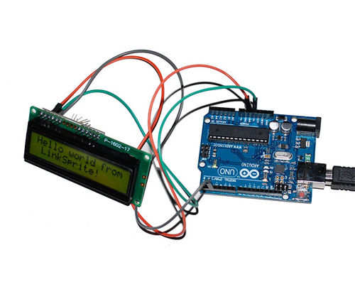
 LCD.print("Hello world from LinkSprite!");
}
void loop() { }
FAQ
Please list your question here:
Support
If you have questions or other better design ideas, you can go to our forum to discuss or creat a ticket for your issue at linksprite support.
Resources
How to buy
See Also
Other related products and resources.
Licensing
This documentation is licensed under the Creative Commons Attribution-ShareAlike License 3.0 Source code and libraries are licensed under GPL/LGPL, see source code files for details.


