Difference between revisions of "PcDuino9 中文"
(No difference)
|
Latest revision as of 05:45, 19 January 2017
Contents
介绍
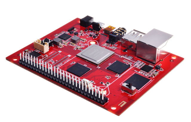
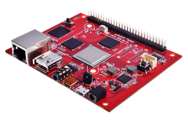
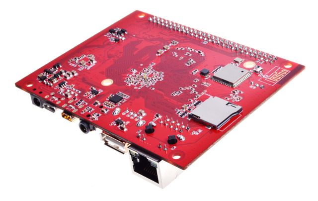
pcDuino9是一个高性能平台,拥有强大的多线程运算能力、图形处理能力以及硬件解码能力,而且它支持 Android和 Ubuntu 双系统,所以它也是一台强大的小型电脑, 我们希望你的创意和灵感能让它变得不平凡。
规格
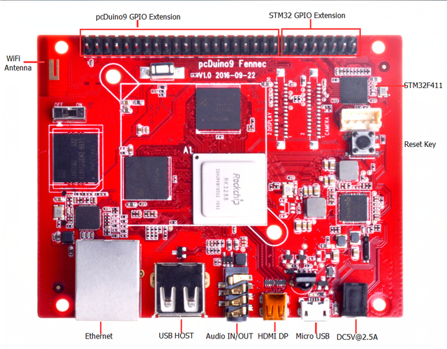
- CPU : Rockchip RK3288 ARM Corte-A17 Quad-Core up to 1.8GHz
- GPU : ARM Mali-T760 MP4 Support OpenGL ES 1.1/2.0 /3.0, OpenVG1.1, OpenCL1.1, Directx11
- Memory : 1GB-4GB Dual-channel 32-bit LPDDR3
- Storage : 8GB-16GB eMMC (Opt.), Micro SD slot support SDXC
- Ethernet : 10/100/1000Mbps Ethernet (RTL8211)
- USB : USB 2.0 Host x 2 (Opt.), USB OTG x 1
- Video : HDMI2.0 support maximum 4K@60Hz display (Micro HDMI), LVDS/MIPI-DSI display interface
- Audio : 3.5mm audio In/Out
- Camera : MIPI-CSI camera interface
- WiFi/BT : AP6212 WiFi + BT module
- GPIO Extension : Raspberry Pi compatible GPIO, support UART, SPI, I2C BMC extension GPIO (Opt.), support ADC, PWM, UART, I2C
- Board Size : 96 x 76 mm
产品参数
- CPU: Rockchip RK3288 ARM Corte-A17 Quad-Core up to 1.8GHz
- GPU: ARM Mali-T760 MP4 Support OpenGL ES 1.1/2.0 /3.0, OpenVG1.1, OpenCL1.1, Directx11
- 内存: 2GB DDR3 双通道
- 存储器 : 16GB eMMC Flash, Micro SD
- 网络 :以太网 -10/100/1000M以太网,无线网 -2.4GHz/5GHz双频WiFi,支持802.11a/b/g/n/ac协议,蓝牙 -Bluetooth 4.0
- 视频输入输出:HDMI2.0 up to 3840x2160@60O ,VGA up to 1080P
- USB : USB2.0 x 1
- IR : 支持红外遥控功能
- 电源 : DC -5V/2.5A
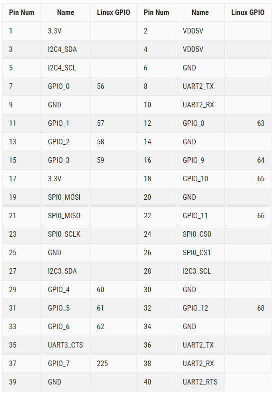
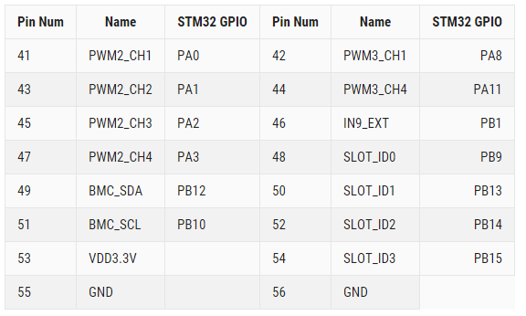
GPIOs 映射
pcDuino9
BMC STM32F411
快速入门
1.在Windows烧写系统到eMMC
a.安装 RK USB 驱动
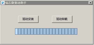
- 下载 DriverAssistant,解压,然后运行里面的DriverInstallexe。
- 为了使所有设备都是用更新的驱动,请选择“驱动卸载”,然后在选择“驱动安装”。
连接设备
- 1.确保设备连接好电源适配器并处于通电状态。
- 2.用 Micro USB OTG 线连接好设备和主机。
- 3.按住设备上的 RECOVERY (恢复)键并保持。
- 4.短按一下 RRESET(复位)键。
- 5.大约两秒钟后,松开 RECOVERY 键。
- 6.注意:如果发现按了 RESET 键后还是没有发现设备,请在保持 RECOVERY 键按下的同时,长按一下 PWRKEY 键,然后才松开 RECOVERY 键。
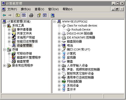
主机应该会提示发现新硬件并配置驱动。打开设备管理器,会见到新设备"Rockusb Device" 出现,如下图。如果没有,则需要返回上一步重新安装驱动。
b.烧写固件
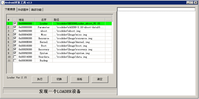
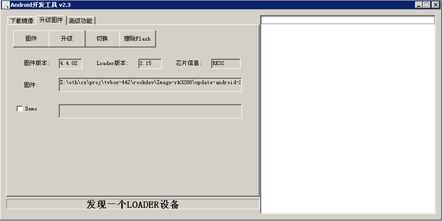
下载AndroidTool,解压,运行里面的AndroidTool.exe(注意,如果是Windows7/8,需要按鼠标右键,选择以管理员身份运行),如下图:
烧写统一固件 xxxx.img 的步骤如下:
- 1.切换至"升级固件"页。
- 2.按"固件"按钮,打开要升级的固件文件。升级工具会显示详细的固件信息。
- 3.按"升级"按钮开始升级。
- 如果升级失败,可以尝试先按"擦除Flash"按钮来擦除 Flash,然后再升级。
注意:如果你烧写的固件laoder版本与原来的机器的不一致,请在升级固件前先执行"擦除Flash"。
烧写分区映像
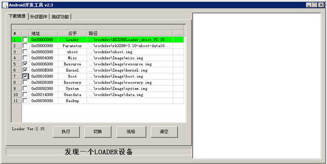
烧写分区映像时,请使用对应SDK下的FFTools/AndroidTool.rar烧写。步骤如下:
- 1.切换至"下载镜像"页。
- 2.勾选需要烧录的分区,可以多选。
- 3.确保映像文件的路径正确,需要的话,点路径右边的空白表格单元格来重新选择。
- 4.点击"执行"按钮开始升级,升级结束后设备会自动重启。
2.在Linux烧写系统到eMMC
RK 提供了一个 Linux 下的命令行工具 upgrade_tool,支持统一固件 update.img 和分区镜像的烧写。
开源工具则有两个选择:
- rkflashtool https://github.com/Galland/rkflashtool_rk3066
- rkflashkit https://github.com/linuxerwang/rkflashkit
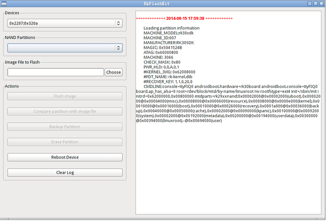
它们都仅支持分区映像烧写,不支持统一固件。rkflashtool 是命令行工具,rkflashkit 有图形界面,后加了命令行支持,更是好用。以下仅对 rkflashkit 做介绍。 Linux 下无须安装设备驱动,参照 Windows 章节连接设备则可。
upgrade_tool
下载 [Linux_Upgrade_Tool Linux_Upgrade_Tool], 并按以下方法安装到系统中,方便调用:
tar xf Linux_UpgradeTool_v1.2.tar.gz
cd Linux_UpgradeTool_v1.2
sudo mv upgrade_tool /usr/local/bin
sudo chown root:root /usr/local/bin/upgrade_tool
烧写统一固件 uxxxx.img:
sudo upgrade_tool uf update.img
烧写分区镜像:
sudo upgrade_tool di -b /path/to/boot.img
sudo upgrade_tool di -k /path/to/kernel.img
sudo upgrade_tool di -s /path/to/system.img
sudo upgrade_tool di -r /path/to/recovery.img
sudo upgrade_tool di -m /path/to/misc.img
sudo upgrade_tool di resource /path/to/resource.img
sudo upgrade_tool di -p paramater   #烧写 parameter
sudo upgrade_tool ul bootloader.bin # 烧写 bootloader
如果因 flash 问题导致升级时出错,可以尝试低级格式化、擦除 nand flash:
sudo upgrade_tool lf   # 低级格式化
sudo upgrade_tool ef   # 擦除
rkflashkit
安装:
sudo apt-get install build-essential fakeroot
git clone https://github.com/linuxerwang/rkflashkit
cd rkflashkit
./waf debian
sudo apt-get install python-gtk2
sudo dpkg -i rkflashkit_0.1.2_all.deb
图形界面:
sudo rkflashkit
命令行:
$ rkflashkit --help
Usage: <cmd> [args] [<cmd> [args]...]
part                              List partition
flash @<PARTITION> <IMAGE FILE>   Flash partition with image file
cmp @<PARTITION> <IMAGE FILE>     Compare partition with image file
backup @<PARTITION> <IMAGE FILE>  Backup partition to image file
erase  @<PARTITION>               Erase partition
reboot                            Reboot device
For example, flash device with boot.img and kernel.img, then reboot:
sudo rkflashkit flash @boot boot.img @kernel.img kernel.img reboot
3.SD卡启动系统
- 下载xxxx.img系统镜像
- 准备一张内存卡(4GB以上C10)
- 使用dd命令将系统复制到SD
- 将卡插在pcDuino9,开机需要按着MASKROM键从TF卡启动
4.pcDuino9硬件操作
硬件操作基于NightWiring 现在它是一个跨平台的C++库控制的硬件接口,包括UART、I2C、SPI和GPIO。大部分的代码是从wiringpi。 GPIO的功能是基于sysfs的现在,这是稍微慢一点,但灵活。
cd nightWiring/
make -j4
sudo make install
GPIO LED控制
#include "nightWiring.h"
#include "nightWiringGPIO.h"
#include "stdio.h"

static int fennecGpioMap[] = {

    /*  GPIO2_A0  */
            56,
    /*  GPIO2_A1,       GPIO2_A2,       GPIO2_A3,       GPIO2_A4    */
            57,             58,             59,             60,
    /*  GPIO2_A5,       GPIO2_A6,       GPIO7_B1,       GPIO2_A7    */
            61,             62,             225,            63,
    /*  GPIO2_B0,        GPIO2_B1,      GPIO2_B2,       GPIO2_B4    */
            64,             65,             66,             68,
    /*  GPIO2_B5,        GPIO7_B0,      GPIO7_A7,       GPIO7_B2    */
            69,             224,            223,            226
};

int ledMap[] = {2, 10, 3, 11};

int main(void)
{
    int i, j;
    nightWiringSetup();
    nightWiringGpioSetup(fennecGpioMap, 17);
    for(i=0; i<4; i++)
        pinMode(ledMap[i], OUTPUT);
    while(1)
    {
        for(i=0; i<4; i++)
        {
            for(j=0; j<4; j++)
                digitalWrite(ledMap[j], HIGH);
            digitalWrite(ledMap[i], LOW);
            delay(500);
        }
    }
    return 0;
}
GPIO 按键输入
#include "nightWiring.h"
#include "nightWiringGPIO.h"
#include "stdio.h"

static int fennecGpioMap[] = {
    /*  GPIO2_A0  */
            56,
    /*  GPIO2_A1,       GPIO2_A2,       GPIO2_A3,       GPIO2_A4    */
            57,             58,             59,             60,
    /*  GPIO2_A5,       GPIO2_A6,       GPIO7_B1,       GPIO2_A7    */
            61,             62,             225,            63,
    /*  GPIO2_B0,        GPIO2_B1,      GPIO2_B2,       GPIO2_B4    */
            64,             65,             66,             68,
    /*  GPIO2_B5,        GPIO7_B0,      GPIO7_A7,       GPIO7_B2    */
            69,             224,            223,            226
};

int keyMap[] = {6, 13, 4, 12, 5};
char keyName[5][7] = {"UP\0", "CENTER\0", "DOWN\0", "LEFT\0", "RIGHT\0"};

int readKey(int num)
{
    int key = digitalRead(keyMap[num]);
    if(key == LOW)
    {
        // Delay for a while and re-detect the key status
        // Filtering glitches on the signal
        delay(10);
        if(key == LOW)
            return 1;
    }

    return 0;
}

int main(void)
{
    int i;
    nightWiringSetup();
    nightWiringGpioSetup(fennecGpioMap, 17);
    for(i=0; i<5; i++)
        pinMode(keyMap[i], INPUT);
    while(1)
    {
        for(i=0; i<5; i++)
        {
            if(readKey(i))
            {
                printf("Key %s is pressed!\n", keyName[i]);
                delay(500);
            }
        }
    }
    return 0;
}
I2C RTC
#include "nightWiring.h"

#include "nightWiringI2C.h"

#include "stdio.h"

#define DS1307_ADDR 0x68

int i2cFd;
int quitFlag = 0;

unsigned char DEC2BCD(unsigned char val)
{
  return ( (val/10*16) + (val%10) );

}

unsigned char BCD2DEC(unsigned char val)
{
   return ( (val/16*10) + (val%16) );
}


void rtcSetTime(unsigned char year, unsigned char month, unsigned char date, unsigned char dayofWeek, unsigned char hour, unsigned char min ,unsigned   char sec)
{
  unsigned char reg = 0x00;
  i2cWriteReg8(i2cFd, 0x00, DEC2BCD(sec));
  i2cWriteReg8(i2cFd, 0x01, DEC2BCD(min));
  i2cWriteReg8(i2cFd, 0x02, DEC2BCD(hour));
  i2cWriteReg8(i2cFd, 0x03, DEC2BCD(dayofWeek));
  i2cWriteReg8(i2cFd, 0x04, DEC2BCD(date));
  i2cWriteReg8(i2cFd, 0x05, DEC2BCD(month));
  i2cWriteReg8(i2cFd, 0x06, DEC2BCD(year));
}

void rtcGetTime()
{
  unsigned char year, month, date, dayofWeek, hour, min ,sec;
  unsigned char reg = 0x00;
  sec       = BCD2DEC(i2cReadReg8(i2cFd, 0x00) & 0x7f);
  min       = BCD2DEC(i2cReadReg8(i2cFd, 0x01));
  hour      = BCD2DEC(i2cReadReg8(i2cFd, 0x02) & 0x3f);
  dayofWeek = BCD2DEC(i2cReadReg8(i2cFd, 0x03));
  date      = BCD2DEC(i2cReadReg8(i2cFd, 0x04));
  month     = BCD2DEC(i2cReadReg8(i2cFd, 0x05));
  year      = BCD2DEC(i2cReadReg8(i2cFd, 0x06));
  printf("Time: %02d-%02d-%02d  %02d:%02d:%02d.\n", year, month, date, hour, min ,sec);
}

int main(void)
{
    int i;
    if((i2cFd=i2cSetup("/dev/i2c-4", DS1307_ADDR)) < 0)
    {
        printf("Error: I2C acess failed! i2cSetup() return %d\n",i2cFd);
        return 0;
    }
    printf("I2C interface init complete.\n");
    printf("Writing time 2016-10-01 Sat 21:10:00 to RTC...\n");
    rtcSetTime(16,10,1,6,21,10,0);
    while(1)
    {
        rtcGetTime();
        delay(1000);
    }
    return 0;
}
