Difference between revisions of "Relay Module"
| Line 1: | Line 1: | ||
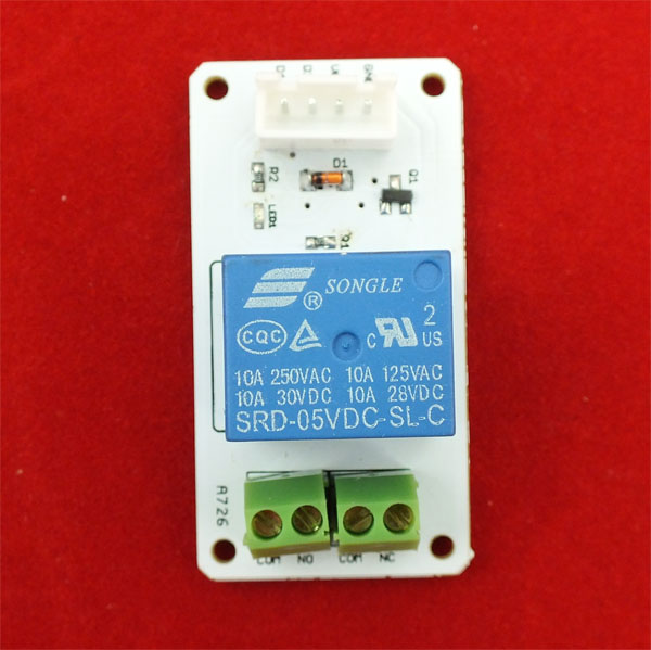
[[File:Linker relay.jpg]] | [[File:Linker relay.jpg]] | ||
| + | |||
| + | == program == | ||
| + | |||
| + | <syntaxhighlight lang="c"> | ||
| + | |||
| + | /* | ||
| + | grove Relay | ||
| + | the Relay will turn on for 5s and then turn off for 5s, and so on. | ||
| + | |||
| + | This example code is in the public domain. | ||
| + | */ | ||
| + | |||
| + | int RelayControlPin = 13; | ||
| + | void setup() { | ||
| + | // initialize the digital pin as an output. | ||
| + | // Pin 13 has an LED connected on most Arduino boards: | ||
| + | pinMode(RelayControlPin, OUTPUT); | ||
| + | } | ||
| + | |||
| + | void loop() { | ||
| + | digitalWrite(RelayControlPin, HIGH); // set the LED on | ||
| + | delay(500); // wait for a second | ||
| + | digitalWrite(RelayControlPin, LOW); // set the LED off | ||
| + | delay(500); // wait for a second | ||
| + | } | ||
| + | |||
| + | |||
| + | </syntaxhighlight> | ||
== Schematics == | == Schematics == | ||
*[https://s3.amazonaws.com/linksprite/LinkerKit/link_relay.pdf Schematics] | *[https://s3.amazonaws.com/linksprite/LinkerKit/link_relay.pdf Schematics] | ||
Revision as of 11:54, 25 April 2013
program
<syntaxhighlight lang="c">
/*
 grove Relay
 the Relay will turn on for 5s and then turn off for 5s, and so on.

 This example code is in the public domain.
*/
int RelayControlPin = 13; void setup() {
 // initialize the digital pin as an output.
 // Pin 13 has an LED connected on most Arduino boards:
 pinMode(RelayControlPin, OUTPUT);
}
void loop() {
 digitalWrite(RelayControlPin, HIGH);   // set the LED on
 delay(500);              // wait for a second
 digitalWrite(RelayControlPin, LOW);    // set the LED off
 delay(500);              // wait for a second
}
</syntaxhighlight>
