Difference between revisions of "Bluetooth Shield for Arduino"
(→Host-Slave mode: Communication between two different Bluetooth shields) |
(→Host-Slave mode: Communication between two different Bluetooth shields) |
||
| Line 204: | Line 204: | ||
At the same time, the following will show up on serial terminal: | At the same time, the following will show up on serial terminal: | ||
| + | |||
| + | [[File:Bluetoothshield host slave 5.jpg]] | ||
Revision as of 21:51, 25 May 2013
Contents
Introduction
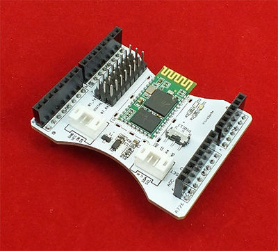
The Bluetooth Shield integrates a Serial Bluetooth module. It can be easily used with Arduino for transparent wireless serial communication. You can choose two pins from Arduino D0 to D7 as Software Serial Ports to communicate with Bluetooth Shield (D0 and D1 is Hardware Serial Port). The shield also has two Grove connectors (one is Digital, the other is Analog) for you to install Grove modules.
Note: The Shield may not be compatible with some Bluetooth capable devices, like some HTC mobile phone (G7 with Android 2.33) and Apple devices with special profile on Bluetooth function.
Features
- Arduino compatible
- Up to 10m communication distance for line-of-sight communication
- UART interface (TTL) with programmable baud rate (SPP firmware installed)
- Default Baud rate: 38400, Data bits: 8, Stop bit: 1, Parity: No parity
- Default PINCODE:”0000”
- A full set of configuration commands
- On board PCB Antenna
Specification
| Item | Min | Typical | Max | Unit |
|---|---|---|---|---|
| Voltage | 2.8 | 3.3 | 3.5 | VDC |
| Current | 3 | / | 100 | mA |
| Communication Distance(in house) | / | / | 10 | m |
| Protocol | Bluetooth V2.0 with SPP firmware | / | ||
| Interface | Uart Serial Port(TTL) | / | ||
| Supported Baudrate | 9600, 19200, 38400, 57600, 115200, 230400, 460800 | bps | ||
| Dimension | 57.4x45.3x19.4 | mm | ||
| Net Weight | 10±2 | g | ||
Quick Test
Host-Slave mode: Communication between two different Bluetooth shields
- Take one Bluetooth shield and do the following:
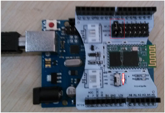
- Select the Bluetooth shield communication port using jumpers: BT_RX is connected to D6 of Digital-6, BT_TX is connected to Digital-7. Move the mode selection switch to lower position so that Bluetooth module will enter into AT command mode.
- Install Bluetooth shield on the Arduino Uno,and plung Arduino into PC, LED D1 on Bluetooth shield will start blinking.
- Copy and paste the following sample code and download to Arduino:
<syntaxhighlight lang="c">
- include <SoftwareSerial.h>
- define RxD 7
- define TxD 6
SoftwareSerial BlueToothSerial(RxD,TxD); void setup() {
  Serial.begin(38400);
  BlueToothSerial.begin(38400);
  delay(500);
} void loop() {
   if(BlueToothSerial.available())
   {
     Serial.print(char(BlueToothSerial.read()));
   }
   if(Serial.available())
   {
     BlueToothSerial.print(char(Serial.read()));
   }
}
</syntaxhighlight>
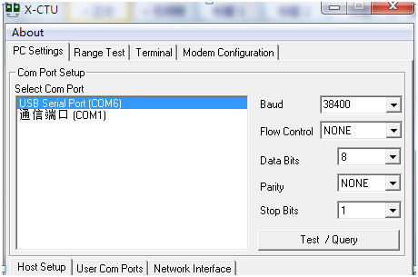
- Launch X-CTU, select the corresponding port, configure the baud rate to be 38400/0/8/N/1. LED-D1 on Bluetooth shield will turn on for about 1 second and turn off.
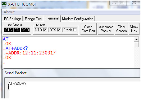
- Send AT command through the UART to check MAC address of the Bluetooth shield ("AT+ADDR?\r\n"), and write down the results. In the following picture, we show that the MAC address is: 12:11:230317.
- In X-CTU, close com port. Now, we download the slave code as shown below:
<syntaxhighlight lang="c">
- include <SoftwareSerial.h>
- define RxD 7
- define TxD 6
SoftwareSerial BlueToothSerial(RxD,TxD); char flag=1; void Test_BlueTooth() {
  unsigned char t=0;
  String RXD = "";
  Serial.println("Test BlueTooth ...");
  BlueToothSerial.print("AT\r\n");
  delay(100);
  while(BlueToothSerial.available()>0)
  {
     RXD +=  char( BlueToothSerial.read() );
     delay(1);
  }
  do{
    t++;
    delay(400);
    Serial.println("Test Failed ! Retrying ...");
  }while( ((RXD[0]!='O')&&(RXD[1]!='K'))&&(t<5));
  if(t<5) Serial.println("Test Successful !\r\n");
  else { Serial.println("Retry Failed !"); while(1); }
}
void sendBlueToothCommand(char *Command) {
 BlueToothSerial.print(Command);
 Serial.print(Command);
 delay(100);
 while(BlueToothSerial.available())
 {
    Serial.print(char(BlueToothSerial.read()));
 }
}
void setupBlueTooth() {
 Serial.println("Bluetooth Initialization ...");
 sendBlueToothCommand("AT+NAME=Slave\r\n");
 sendBlueToothCommand("AT+ROLE=0\r\n");
 sendBlueToothCommand("AT+CMODE=1\r\n");
 sendBlueToothCommand("AT+PSWD=1234\r\n");
 sendBlueToothCommand("AT+UART=38400,0,0\r\n");
 delay(500);
 Serial.println("Bluetooth Initialized Successfully !\r\n");
 do{
   if(Serial.available())
   {
     if( Serial.read() == 'S')
     {
       sendBlueToothCommand("AT+RESET\r\n");
       flag = 0;
     }
   }
 }while(flag);
}
void setup() {
  Serial.begin(38400);
  BlueToothSerial.begin(38400);
  delay(500);
  Test_BlueTooth();
  setupBlueTooth();
}
void loop() {
   if(BlueToothSerial.available())
   {
     Serial.print(char(BlueToothSerial.read()));
   }
   if(Serial.available())
   {
     BlueToothSerial.print(char(Serial.read()));
   }
}
</syntaxhighlight>
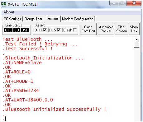
- Go back to X-CTU, and open the com port again. The baud rate setting is still 38400/0/8/N/1. Now the LED D1 on bluetooth shield will start blinking at a period of around 2 seconds. At the same time, the serial port will output something like the following:
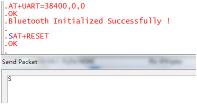
- Now we move the mode switch the upper position, which is 'NC'. Send upper case 'S', and the bluetooth module will enter into normal mode, and LED-D1 will start blinking at a frequency of once per 0.2 second, which means that Bluetooth module has finished the initialization.
At the same time, the following will show up on serial terminal:
