Difference between revisions of "Tilt Module"
Qian.zhang (talk | contribs) (→Schematics) |
Qian.zhang (talk | contribs) (→Features) |
||
| Line 6: | Line 6: | ||
== Features == | == Features == | ||
| − | Dimensions: | + | Dimensions: 27.9×25.4×10.6mm |
Net weight: 3.6g | Net weight: 3.6g | ||
| + | |||
| + | == Dimension == | ||
| + | |||
| + | [[File:tilt dimension.jpg]] | ||
== Schematics == | == Schematics == | ||
Revision as of 06:10, 16 June 2014
Introduction
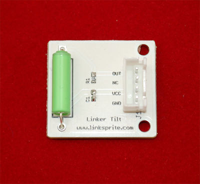
The Linker Tilt Module is the equivalent of a button, and is used as a digital input. Inside the tilt switch is a pair of balls that make contact with the pins when the case is upright. Tilt the case over and the balls don't touch, thus not making a connection. It is wired to the SIG line, NC is not used on this kit.
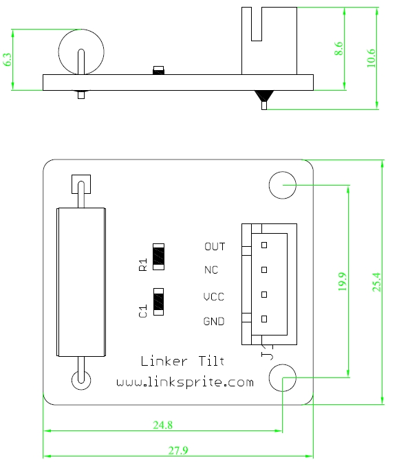
Features
Dimensions: 27.9×25.4×10.6mm
Net weight: 3.6g
Dimension
Schematics
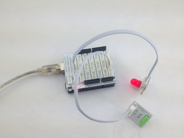
Application Ideas
<syntaxhighlight lang="c">
int ledPin = 13; int switchPin = 7; int val = 0; void setup() {
 pinMode(ledPin,OUTPUT);
 pinMode(switchPin,INPUT);
} void loop() {
 //digitlRead(switchPin,HIGH)
 val = digitalRead(switchPin);
 if (HIGH == val)  digitalWrite(ledPin,HIGH);
 else  digitalWrite(ledPin,LOW);
}
</syntaxhighlight>
How to buy
Here to buy Tilt Module on store


