Difference between revisions of "Acrylic Frame Robot Platform"
Qian.zhang (talk | contribs) (→Assembly Instructions) |
Qian.zhang (talk | contribs) (→Assembly Instructions) |
||
| Line 33: | Line 33: | ||
*Use 2 M3*12 screws to fix Ball Caster Metal on Acrylic Bottom Plate. | *Use 2 M3*12 screws to fix Ball Caster Metal on Acrylic Bottom Plate. | ||
| − | [[File:Acrylic robot | + | [[File:Acrylic robot platform2.jpg]] |
*Use 2 M3*12 screws to fix Batter Case on Acrylic Bottom Plate. | *Use 2 M3*12 screws to fix Batter Case on Acrylic Bottom Plate. | ||
Revision as of 07:35, 27 August 2014
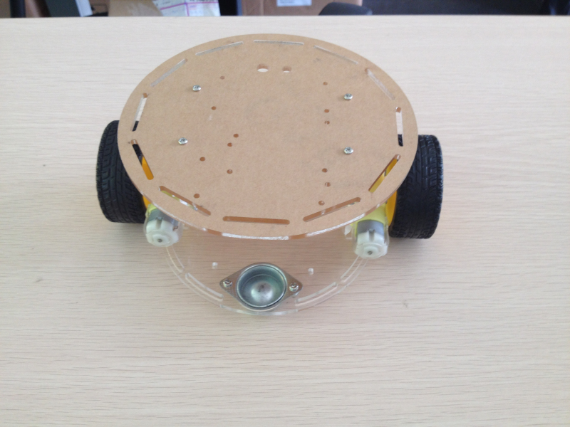
Introduction
Package List
- 1 × Acrylic Top Plate [IT_KIT_ACRYTOPPL]] [CA101102]
- 1 × Acrylic Bottom Plate [IT_KIT_ACRYBOTTPL] [CA101103]
- 1 × Acrylic Connecting Plate(5 holes) [IT_KIT_ACRY CONNPL5HO][CA101104]
- 1 × Acrylic Connecting Plate(6 holes) [IT_KIT_ACRY CONNPL6HO][CA101105]
- 2 × Motor [IT_MOTOR_DC3V_6V] [WH103101]
- 2 × Wheel [IT_TIRE_A] [WH101102]
- 10× Jumper Wires [IT_JUMR_MM_PK40_WI20CM][BB101104]
- 1 × Acrylic Web Cam Plate [IT_ACRY_WEDCAMPL] [CA101106]
- 1 × Battery Case [IT_BYPS_6_5][WH104101]
- 16× Screw 3mm*6 [IT_SCREW_6MM] [WB101102]
- 16× Screw 3mm*12 [IT_SCREW_12MM] [WB101103]
- 4 × Screw 3mm*25 [IT_SCREW_25MM] [WB101104]
- 1 × Ball Caster Metal [BOT_PT_OMNIDMETAL][104201008]
- 8 × Copper Pillar [IT_COPPCYL_6MM] [WA101102]
- 24× M3 Nut [IT_NUT_3M][WB101101]
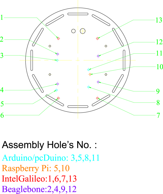
Explanation of Acrylic Top Plate
Assembly Instructions
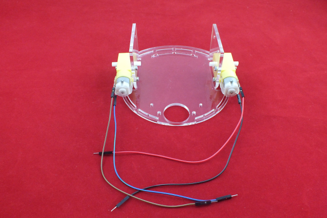
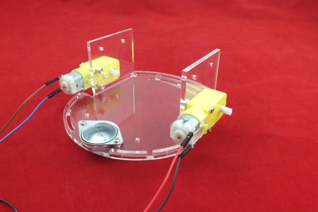
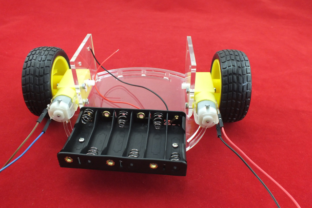
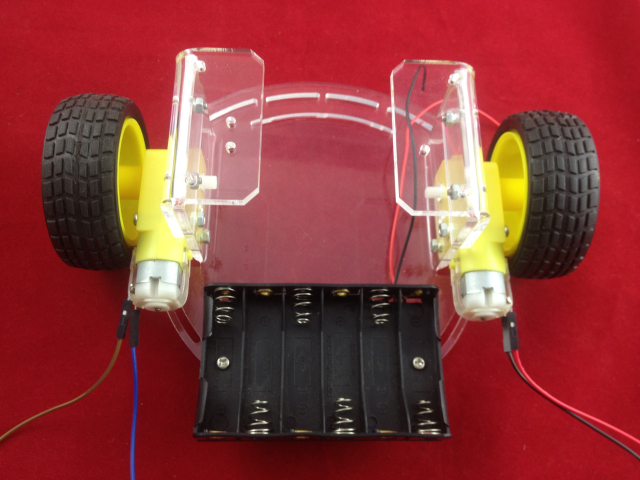
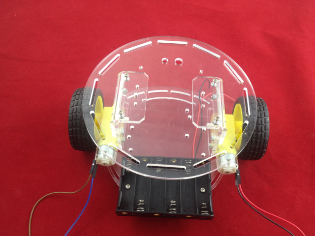
- Solder Jumper Wires on both DC Motors. Use 4 M3*25 screws to fix the DC motors on Acrylic Bottom Plate, note that the bump of DC motors should be aimed to the holes on Acrylic Bottom Plate.
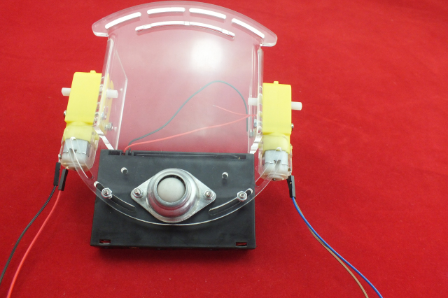
- Use 2 M3*12 screws to fix Ball Caster Metal on Acrylic Bottom Plate.
- Use 2 M3*12 screws to fix Batter Case on Acrylic Bottom Plate.
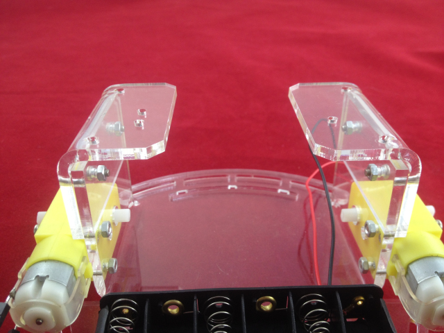
- Use 2 M3*12 screws to fix Acrylic Connecting Plate(6 holes) on the left side(from top view, the battery case is at bottom) of Acrylic Bottom Plate, use another 2 M3*12 screws to fix Acrylic Connecting Plate(5 holes) on the other side.
- Use 4 M3*12 screws to fix Acrylic Top Plate on Acrylic Bottom Plate.
