Difference between revisions of "Spruce"
(→How to buy) |
Yajuan.dai (talk | contribs) (→Introduction) |
||
| Line 3: | Line 3: | ||
Spruce has Arduino compatible shield pins, all the Arduino shields can be used on LinkSprite STM32 cortex board. Arduino similar IDE can be used to download Arduino code to Spruce board. | Spruce has Arduino compatible shield pins, all the Arduino shields can be used on LinkSprite STM32 cortex board. Arduino similar IDE can be used to download Arduino code to Spruce board. | ||
| − | |||
| − | |||
| − | |||
| − | |||
*model:MP_SPRUCE_WOLCD | *model:MP_SPRUCE_WOLCD | ||
Latest revision as of 08:18, 28 August 2014
Contents
Introduction
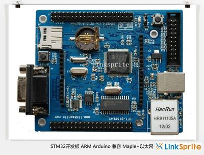
Spruce -LinkSprite STM32 ARM cortex board can be used with OpenJTAG and is compatible withmini ARM cortex-M3 board . It can be used in GCC+Eclipse+openocd+openJtag and Arduino enviroment! When used in Arduino enviroment, it is compatible with Maple.
Spruce has Arduino compatible shield pins, all the Arduino shields can be used on LinkSprite STM32 cortex board. Arduino similar IDE can be used to download Arduino code to Spruce board.
- model:MP_SPRUCE_WOLCD
Spruce Hardware Resource
- CPU: STM32F103VET6, TQFP 100 pins FLASH:512K BYTES, SRAM:64KBYTES
- 1 JTAG debug interface
- 1 power LED indicattor (Green), 1 status LED (Blue)
- 1 RS232 port, Need crossover cable to talk to PC
- Support 3 pin ISP
- 1 USB2.0 SLAVE port
- 1 Micro SD(TF) slot, uses SDIO
- 1 SPI interfaced AT45DB161D(2M BYTES) serial FLASH
- 1 functional botton
- 1 RTC battery socket
- 1 RJ45 Ethernet port
- All unused GPIO pins are connected to external headers.
- LCD NOT INCLUDED
Arduino IDE Environment
In Arduino IDE enviroment, it is fully compatible with maple, and all arduino shield. The bootloader is flashed through RS232 port, and the arduino program is downloaded frm USB port. The driver of the USB port can be found at the maple IDE, which can be downloaded from the maple IDE version for Spruce.
GCC+Eclipse+OpenOCD+OpenJTAG
Spruce also supports development using GCC+Eclipse+OpenOCD+OpenJTAG.
Schematic
Eclipse Enviroment Setup and User Guide
Eclipse is a Java development enviroment, but its architecture also supports other languages. In this article we will introduce how to use C/C++ development Toolkit CDT) together with Sourcery G++ Lite for ARM EABI to do embedded ARM development work,
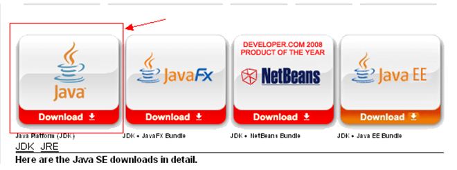
We need to install JAVA JDK before install Eclipse. The JAVA JDK can be downloaded from:download
After registration, we can download jdk-6u22-windows-i586.exe and install.
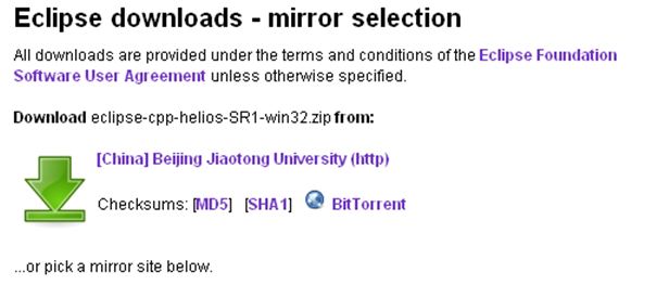
Download Eclipse IDE for C/C++ Developers, it has Eclipse and CDT. The download link is: Eclipse IDS
Select Eclipse IDE for C/C++ Developers,
After download, unzip eclipse and run Eclipse.
Install ARM plug-in for Eclipse:
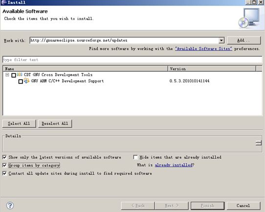
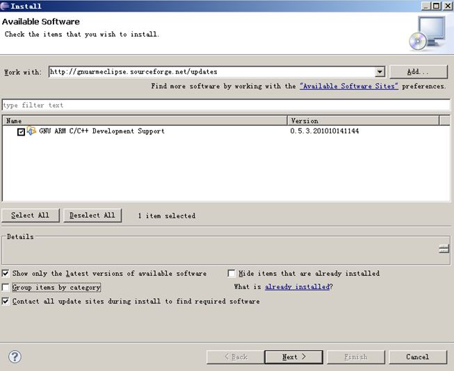
In menu, select Help – > Install New Software, and enter:
http://gnuarmeclipse.sourceforge.net/updates
in the "work with" address bar:
After several seconds, it will display GNU ARM C/C++ Development Support, click GNU ARM C/C++ Development Support, and unclick Group items by category:
Click Next untill Finish, and wait for the downloading update.
In menu, select " Help – > Install New Software" and enter http://www.zylin.com/zylincdt in "work with".
After several seconds, it will display an option " Zylin Embedded CDT". Select it and click "next" until "finish", wait for downloading.
Install Sourcery G + + Lite
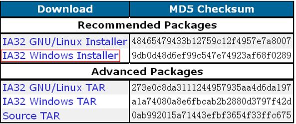
It can be downloaded from:Download
Select IA32 windows installer.
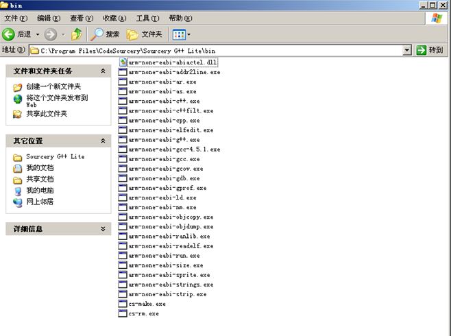
Download arm-2010q1-188-arm-none-eabi.exe. After finish installation, we have:
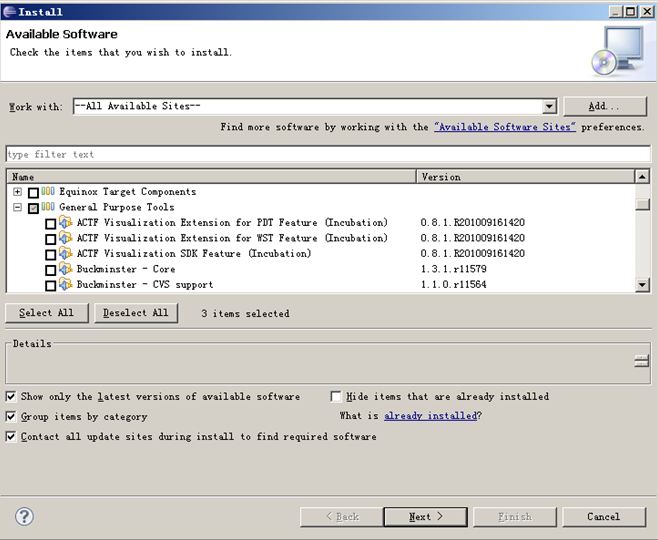
Install remote support by doing: Help – > Install New Software, and select " All Available Sites" in "Work with" pull down menu. Select " Group items by category" option, and select
General Purpose Tools
- Dynamic Languages Toolkit – Remote Development Support
- Remote System Explorer End-User Runtime
- Remote System Explorer User Actions
Create new project
We can now create new project " Sourcery G++ Lite" in menu "File", and do compilation and link.
- 1. Run eclipse, and select the location of the newly created project file " workspace".
- 2. Creat a new project " Sourcery G++ Lite" project:
input porject name under "File->new->c project->", and select " Sourcery G++->finish" in " toolchains":
- 3. add files to project, and edit application file.
Right click project file name, and select "refresh" to load the changed file directory to "Eclipse".
- 4. Set properties:
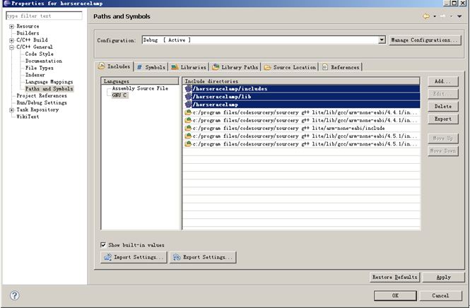
Right click project file name and select " properties" ->C/C++ General->paths and symbols->, select " GNU C->add->workspace-> inlude " under " GNU C->add->workspace->", and ->apply ( ok )。
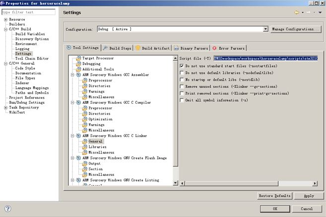
"properties" ->C/C++ Build->settings->, and select " ARM Sourcery Windows GCC Linker ->General->" under " ARM Sourcery Windows GCC Linker ->General->", and select (*.ld)- in " script file", ->ok .
Enter the absolute path of .ld file.
- 5. Build
Right click project file and click " build project" or " clean project "
Spruce Used to Control LinkSprite Robot Platform
On LinkSprite Spruce, STM32 MCU is used. STM32 has ARM Cortex-M3 core. It can be used on Keil development environment and Arduino IDE.
LinkSprite Arduino Robotics Kit is an Arduino based Robotics kit.
The hardware included:
- Robotics platform
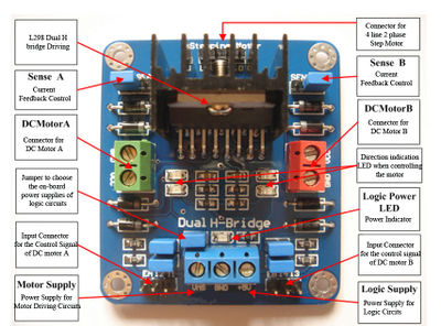
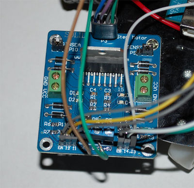
- Two-Channel DC Motor Driver Breakout (L298 Chipset)
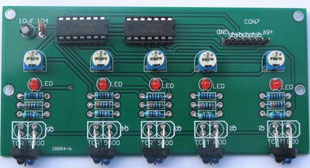
- Path sensor board
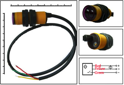
- three infrared obstacle sensors
- Arduino board is NOT included
- Battery holder
- Jumper wires
The platform comes with the metal base, two rubber tires, one ball caster metal, and two gearmotors.
Connection instructions
Two-Channel DC Motor Driver Breakout to Arduino Uno:
- I1 -> pin 2 of spruce
- I2 -> pin 1 of spruce
- I3 -> pin 5 of spruce
- I4 -> pin 6 of spruce
- EA -> pin 11 of spruce
- EB -> pin 12 of spruce
P3 on the motor driver board is connected to the four wires of two motors. VMS is connected to the Vin of Arduino, and GND is connected to the ground of Arduino.
Path Sensor Breakout Board connected to Arduino:
- +5V is connected to 5V on Arduino.
- GND is connected to ground on Arduino.
- Pin 15 connected to Q1
- Pin 16 connected to Q2
- Pin 17 connected to Q3
- Pin 18 connected to Q4
- Pin 19 connected to Q5
Obstacle sensors connected to Arduino:
- Front obstacle sensor connected to Pin 16.
- Right obstacle sensor connected to Pin 17.
- Left obstacle sensor connected to Pin 15.
Path following example
After switch on,the car will run along the black line on floor , this car is equipped with five path sensors, when the middle sensor detectes black line, car will go forward; when the centreright sensor detectes black line, that indicate car will slightly turn to the right side, so the car should be turned slightly to the left; when the most right sensor detects black line, that indicate car turn too much to the right side, so the car should turn left by a wide margin. Concretely, use PWM control L298N end EA, EB can be enabled to control car's speed, by controlling delay () to control car's rotation angle. By analogy, the black line wich detected by left side sensor will be just opposite.
Arduino PDE example:
<syntaxhighlight lang="c"> unsigned char road=0; void setup() { pinMode(1,OUTPUT); pinMode(2,OUTPUT); pinMode(4,OUTPUT); pinMode(5,OUTPUT); pinMode(11,PWM); pinMode(12,PWM); pinMode(15, INPUT); pinMode(16, INPUT); pinMode(17, INPUT); pinMode(18, INPUT); pinMode(19, INPUT); Serial1.begin(9600); } void loop() { Serial1.write("Arduino!\r\n"); //////////////////////////////////////////// road = digitalRead(15)+digitalRead(16)*2+digitalRead(17)*4+ digitalRead(18)*8+digitalRead(19)*16; switch (road) { case 0b00011011: forward(); delay(100); break; /////////////////////////////////////////// case 0b00011101: turn_left(); pwmWrite(11,17000); delay(50); break; case 0b00010111: turn_right(); pwmWrite(12,17000); delay(50); break; //////////////////////////////////////// case 0b00001111: turn_right(); delay(50); break; case 0b00011110: turn_left(); delay(50); break; /////////////////////////////////// default: forward(); delay(10); } } void turn_left(void) { digitalWrite(1,LOW); digitalWrite(2,HIGH); digitalWrite(4,HIGH); digitalWrite(5,LOW); pwmWrite(11,35000); pwmWrite(12,35000); } void turn_right(void) { digitalWrite(1,HIGH); digitalWrite(2,LOW); digitalWrite(4,LOW); digitalWrite(5,HIGH); pwmWrite(11,35000); pwmWrite(12,35000); } void forward(void) { digitalWrite(1,HIGH); digitalWrite(2,LOW); digitalWrite(4,HIGH); digitalWrite(5,LOW); pwmWrite(11,35000); pwmWrite(12,35000); } void back(void) { digitalWrite(1,LOW); digitalWrite(2,HIGH); digitalWrite(4,LOW); digitalWrite(5,HIGH); pwmWrite(11,17000); pwmWrite(12,17000); }
</syntaxhighlight>
Get out of Maze example
Equipped with three infrared sensors at the front of the car to avoid obstacles, when an obstacle is detected, the corresponding sensor will output low level. When obstacle is detected at current side, the car will backward a little then turn left again by default; when right side of the obstacle is detected, the car will turn to left; when left obstacle is detected, the car will turn to right. Attention that each rotation rate shouldn't be too much, you can use the program for several minor adjustments, so that car can move ahead closely to the edge of obstacle, Concretely,use the PWM control L298N Enable EA, EB to control car's speed, by controlling delay ()to control car's rotation angle. You can adjust the potentiometer on the back of sensor to adjust the detection range, detection distance shouldn't too far, the appropriate distance is 20CM, thus the car can achieve Maze features, if encountered a dead end, car can come out closely to the wall.
Arduino PDE:
<syntaxhighlight lang="c"> unsigned char status=0; void setup() { pinMode(1,OUTPUT); pinMode(2,OUTPUT); pinMode(5,OUTPUT); pinMode(6,OUTPUT);
pinMode(15,INPUT); pinMode(16,INPUT); pinMode(17,INPUT); pinMode(11, PWM); pinMode(12, PWM); } void loop() { status = digitalRead(15)+digitalRead(16)*2+digitalRead(17)*4; switch (status) { case 0b00000000: case 0b00000101: back(); delay(100); turn_right(); pwmWrite(12,15000); delay(100); break; /////////////////////////////////////////// case 0b00000001: case 0b00000011: case 0b00000010: turn_right(); pwmWrite(12,15000); delay(10); break; //////////////////////////////////////// case 0b00000100: case 0b00000110: turn_left(); pwmWrite(11,15000); delay(10); break; /////////////////////////////////// /* case 0b00000111: forward(); delay(30); break;*/ /////////////////////////////////// default: forward(); delay(20); } } void turn_left(void) { digitalWrite(1,LOW); digitalWrite(2,HIGH); digitalWrite(5,HIGH); digitalWrite(6,LOW); pwmWrite(11,30000); pwmWrite(12,30000); } void turn_right(void) { digitalWrite(1,HIGH); digitalWrite(2,LOW); digitalWrite(5,LOW); digitalWrite(6,HIGH); pwmWrite(11,30000); pwmWrite(12,30000); } void forward(void) { digitalWrite(1,HIGH); digitalWrite(2,LOW); digitalWrite(5,HIGH); digitalWrite(6,LOW); pwmWrite(11,28000); pwmWrite(12,30000); } void back(void) { digitalWrite(1,LOW); digitalWrite(2,HIGH); digitalWrite(5,LOW); digitalWrite(6,HIGH); pwmWrite(11,30000); pwmWrite(12,30000); }
</syntaxhighlight>
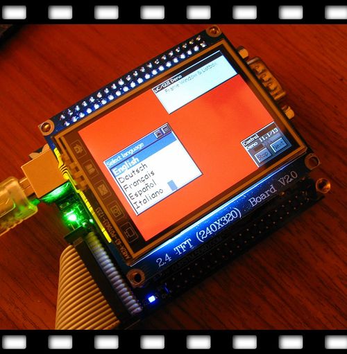
ucGUI Demo
FAQ
Please list your question here:
Support
If you have questions or other better design ideas, you can go to our forum to discuss or creat a ticket for your issue at linksprite support.
Resources
- Quick Start -- Spruce Arduino Bootloader Upload
- IDE and bootloader source files
- OpenJTAG on Spruce board
- Schematics of the TFT LCD
- Sample project files
- Tools Download
How to buy
Here to buy Spruce on store
See Also
Other related products and resources.
Licensing
This documentation is licensed under the Creative Commons Attribution-ShareAlike License 3.0 Source code and libraries are licensed under GPL/LGPL, see source code files for details.
