Difference between revisions of "LED Matrix Kit"
Katherine.d (talk | contribs) (→Testing Steps) |
Katherine.d (talk | contribs) (→Usege) |
||
| Line 90: | Line 90: | ||
==Usege== | ==Usege== | ||
| − | ===Hardware Preparation (Use Arduino as microcontroller) | + | ===Hardware=== |
| + | |||
| + | '''Hardware Preparation (Use Arduino as microcontroller)''' | ||
*LED matrix module | *LED matrix module | ||
| Line 110: | Line 112: | ||
*Power supply 5V/2A. | *Power supply 5V/2A. | ||
| − | + | '''Connection Wires''' | |
The schematics of the LED matrix is attached below. | The schematics of the LED matrix is attached below. | ||
| Line 126: | Line 128: | ||
''Schematics of the 8x8 LED Matrix'' | ''Schematics of the 8x8 LED Matrix'' | ||
| − | + | '''Testing Steps''' | |
1.connecting | 1.connecting | ||
Revision as of 09:31, 30 November 2012
Contents
Introduction
This product is a serially driven 8x8 LED Matrix kit powered by MAX7219.
It only needs three data lines and two power lines.
The 8x8 LED Matrix is easy to use and compatible with Arduino, and its LED brightness adjustment can be implemented in software.
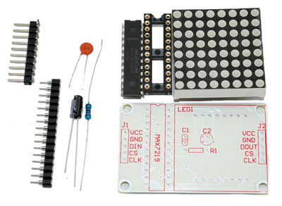
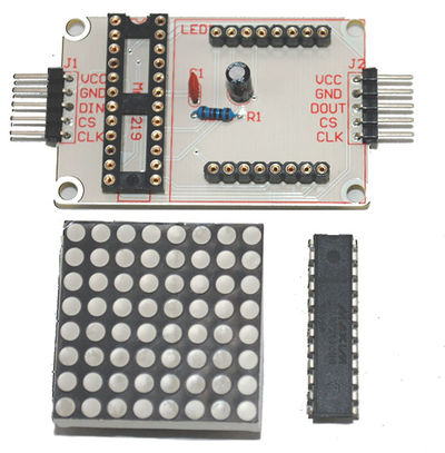
This product comes in the form of a kit. It includes the following components:
- MAX7219
- Electrolytic cpaacitor:10uF/25V
- Resistor:10K
- Capacitance:0.1uF
- Headers and receptacles.
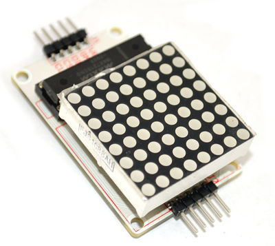
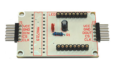
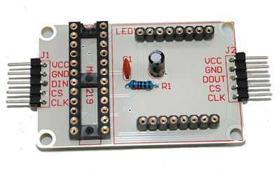
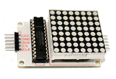
After assembling, it will look as:
Specification of LED Matrix
- Operating Voltage: DC 4.7V – 5.3V
- Typical Voltage: 5V
- Operating Current: 320mA
- Max Operating Current: 2A
- Operating Temperature: 0 ℃ – 50 ℃
- Typical Temperature: 25 ℃
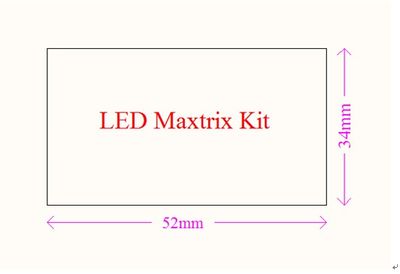
DIMENSIONS
Assembly Instruction
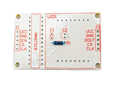
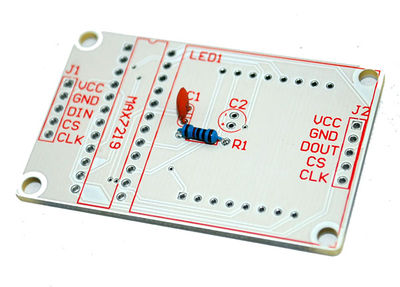
Step 1
- Install resistor R1.
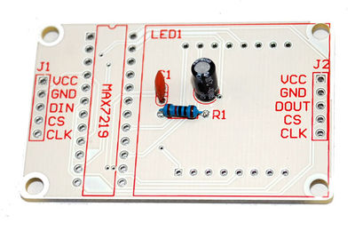
Step 2
- Install capacitor C1.
Step 3
- Install capacitor C2.
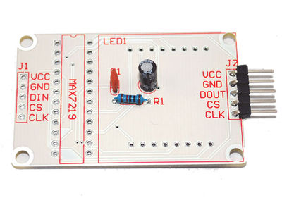
Step 4
- Install header J2.
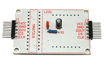
Step 5
- Install header J1.
Step 6
- Install LED matrix receptacle.
Step 7
- Install LED MAX7219 receptacle.
Step 8
- Lay down C2, and install the MAX7219 and LED matrix to their receptacles.
Finally, we get the finished LED matrix module:
Usege
Hardware
Hardware Preparation (Use Arduino as microcontroller)
- LED matrix module
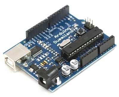
- Arduino
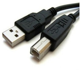
- USB Cable
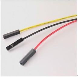
- Jumper Wires
- Power supply 5V/2A.
Connection Wires
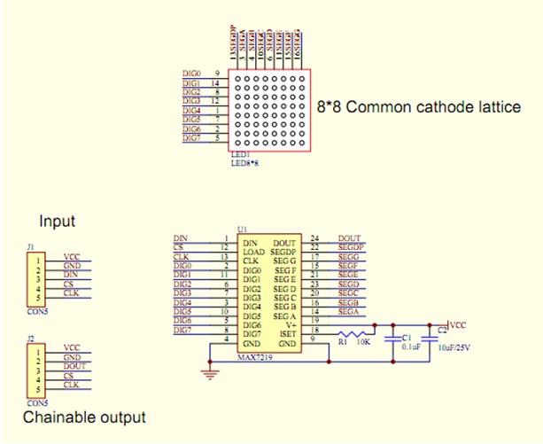
The schematics of the LED matrix is attached below.
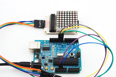
Please follow the following instructions to connect hardwares.
- The 8x8 LED Matrix must be common-grounded with the Arduino module;
- Connect Arduino pin 8 to DIN on the LED Matrix;
- Connect Arduino pin 9 to CS on the LED Matrix;
- Connect Arduino pin 10 to CLK on the LED Matrix;
- Use independent power supply for the 8x8 LED Matrix Shield, and the supply voltage is 5V/2A.
Schematics of the 8x8 LED Matrix
Testing Steps
1.connecting
- Connect Arduino pin8 to DIN on 8*8LED Matrix
- Connect Arduino pin9 to CS on 8*8LED Matrix
- Connect Arduino pin10 to CLK on 8*8LED Matrix
Attention:8*8LED Matrix must be common-grounded with Arduino module.
2.Check the corresponding interfaces are properly connected.
3.Powering up the Arduino demo board with AC adapter.
4.Observation:The LED matrix should circularly display the digits 0 to 9 on LED screen first, then the characters A to Z, as shown in the above figure.
