Difference between revisions of "ADC breakout board for pcDuino8 UNO"
(Created page with " == Description == File:1-97.jpg This ADC breakout board is specially designed for pcDuino8 Uno which has no on-board ADC module. It expands 6 ADC channels using ADI AD7...") |
|||
| Line 2: | Line 2: | ||
== Description == | == Description == | ||
| − | [[File:1-97. | + | [[File:1-97.png]] |
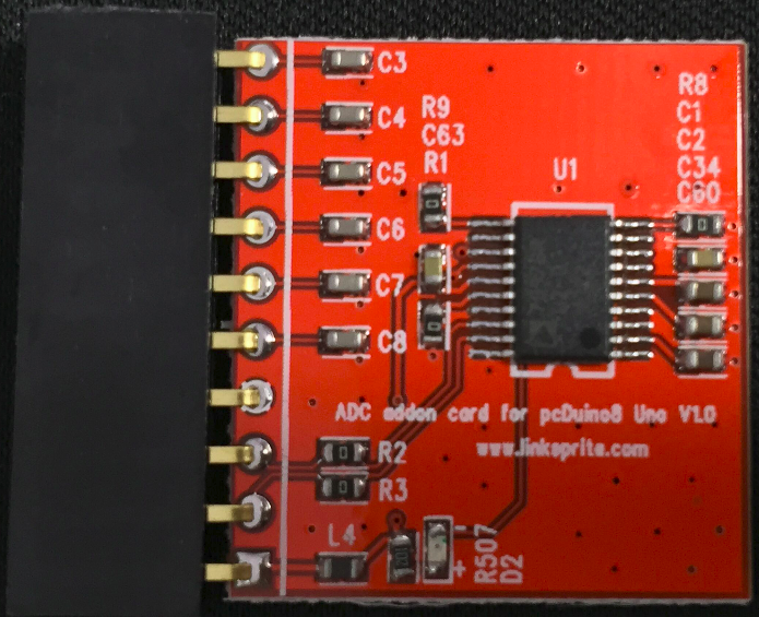
This ADC breakout board is specially designed for pcDuino8 Uno which has no on-board ADC module. It expands 6 ADC channels using ADI AD7997 12-bit ADC module which provides a I2C-compatible interface. | This ADC breakout board is specially designed for pcDuino8 Uno which has no on-board ADC module. It expands 6 ADC channels using ADI AD7997 12-bit ADC module which provides a I2C-compatible interface. | ||
| Line 21: | Line 21: | ||
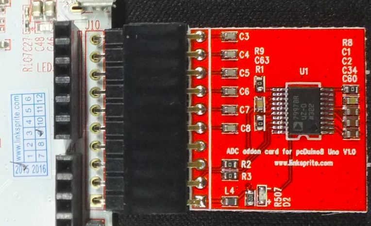
* Plug the ADC breakout board into J10 (as shown in the following picture). | * Plug the ADC breakout board into J10 (as shown in the following picture). | ||
| − | [[File:1-98. | + | [[File:1-98.png]] |
=== Quick test === | === Quick test === | ||
| Line 30: | Line 30: | ||
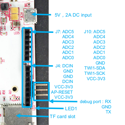
<tt>bash git clone https://github.com/pcduino/pcduino8_uno_lib</tt> * Clean and Compile the lib: <tt>cd pcduino8_uno_lib make clean make sudo ./output/adc_test</tt> * Input an analog signal on ADC0 channel | <tt>bash git clone https://github.com/pcduino/pcduino8_uno_lib</tt> * Clean and Compile the lib: <tt>cd pcduino8_uno_lib make clean make sudo ./output/adc_test</tt> * Input an analog signal on ADC0 channel | ||
| − | [[File:1-99. | + | [[File:1-99.png]] |
* The adc_test program will print the value of analog signal on ADC0 channel as default. | * The adc_test program will print the value of analog signal on ADC0 channel as default. | ||
Revision as of 04:57, 19 February 2016
Contents
Description
This ADC breakout board is specially designed for pcDuino8 Uno which has no on-board ADC module. It expands 6 ADC channels using ADI AD7997 12-bit ADC module which provides a I2C-compatible interface.
Feature
- ADI AD7997 12-bit ADC chip
- 10- and 12-bit ADC
- 8 single-ended analog input channels (Only use 6 channels)
- I2C-compatible serial interface
- 3.3V power supply
Tutorial
Connect to pcDuino8 Uno
- Solder 90° 10-pins headers on J10 of pcDuino8 Uno
- Plug the ADC breakout board into J10 (as shown in the following picture).
Quick test
- Install additional package(s) before use pcduino8_uno_lib on pcDuino8 Uno bash sudo apt-get install libi2c-dev i2c-tools
- Fetch the Arduino lib for pcDuino8 Uno
bash git clone https://github.com/pcduino/pcduino8_uno_lib * Clean and Compile the lib: cd pcduino8_uno_lib make clean make sudo ./output/adc_test * Input an analog signal on ADC0 channel
- The adc_test program will print the value of analog signal on ADC0 channel as default.
Create your own source code for ADC
Create new .c files in samples folder and modify Makefile to compile it. For example I want to create helloADC.c to read the values from all six ADC channels. * Create helloADC.c source file vim samples/helloADC.c
c #include <core.h> int adc_id = 0; void setup() { } void loop() { for(adc_id=0; adc_id<6; adc_id++) { int value = analogRead(adc_id); // get adc value printf("ADC%d value is %d\n",adc_id, value); delay(1000); // wait for one sec } } * Update Makefile bash vim samples/makefile * Add a line after OBJS=… and add the name of your program (without suffix ‘.c’). makefile OBJS = i2c_rtc_test spi_nfc_test adc_test led_test OBJS += uart_test OBJS += helloADC * Compile and run: make sudo output/helloADC Note: If you have not used the latest system image for pcDuino8 Uno, you have to add sudo to access adc , the following content will tell you how to add permission for user linaro. bash sudo echo "SUBSYSTEM=="i2cdev", GROUP="i2c"" > /etc/udev/rules.d/90-i2c.rules sudo useradd linaro i2c sudo reboot


