Photo Cell Sensor
Contents
[hide]Introduction
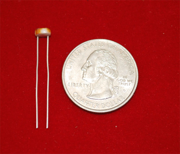
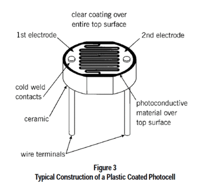
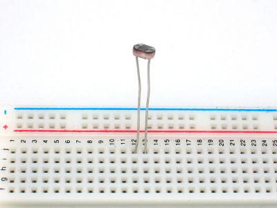
Photocells are sensors that allow you to detect light. They are small, inexpensive, low-power, easy to use and don't wear out. For that reason they often appear in toys, gadgets and appliances. They are often referred to as CdS cells (they are made of Cadmium-Sulfide), light-dependent resistors (LDR), and photoresistors.
For most light-sentsitive applications like "is it light or dark out", "is there something in front of the sensor (that would block light)", "is there something interrupting a laser beam" (break-beam sensors), or "which of multiple sensors has the most light hitting it", photocells can be a good choice!
Features
- 2.54mm general interface
- Wide supply voltage range: 3V–30V
- 2.0cm x 2.0cm module
- Application fields widely
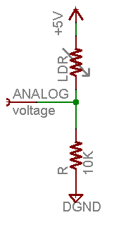
Schematic
Specifications
- Size: Round, 5mm (0.2") diameter. (Other photocells can get up to 12mm/0.4" diameter!)
- Resistance range: 200KΩ (dark) to 10KΩ (10 lux brightness)
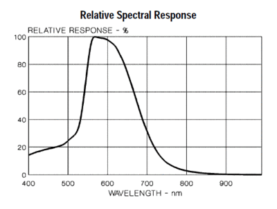
- Sensitivity range: CdS cells respond to light between 400nm (violet) and 600nm (orange) wavelengths, peaking at about 520nm (green).
- Power supply: pretty much anything up to 100V, uses less than 1mA of current on average (depends on power supply voltage)
Measuring Light
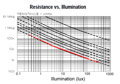
As we've said, a photocell's resistance changes as the face is exposed to more light. When its dark, the sensor looks like an large resistor up to 10MΩ, as the light level increases, the resistance goes down. This graph indicates approximately the resistance of the sensor at different light levels. Remember each photocell will be a little different so use this as a guide only
Note that the graph is not linear, its a log-log graph!
Photocells, particularly the common CdS cells that you're likely to find, are not sensitive to all light. In particular they tend to be sensitive to light between 700nm (red) and 500nm (green) light.
Usage
Connecting a Photocell
Because photocells are basically resistors, they are non-polarized. That means you can connect them up 'either way' and they'll work just fine!
Photocells are pretty hardy, you can easily solder to them, clip the leads, plug them into breadboards, use alligator clips, etc. The only care you should take is to avoid bending the leads right at the epoxied sensor, as they could break off if flexed too often.
Using a Photocell
Analog Voltage Reading Method
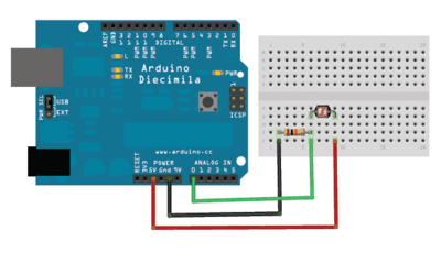
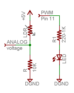
The easiest way to measure a resistive sensor is to connect one end to Power and the other to a pull-down resistor to ground. Then the point between the fixed pulldown resistor and the variable photocell resistor is connected to the analog input of a microcontroller such as an Arduino (shown)
For this example I'm showing it with a 5V supply but note that you can use this with a 3.3v supply just as easily. In this configuration the analog voltage reading ranges from 0V (ground) to about 5V (or about the same as the power supply voltage).
The way this works is that as the resistance of the photocell decreases, the total resistance of the photocell and the pulldown resistor decreases from over 600KΩ to 10KΩ. That means that the current flowing through both resistors increases which in turn causes the voltage across the fixed 10KΩ resistor to increase. Its quite a trick!
| Ambient light like… | Ambient light (lux) | Photocell resistance (Ω) | LDR + R (Ω) | Current thru LDR +R | Voltage across R |
|---|---|---|---|---|---|
| Dim hallway | 0.1 lux | 600 KΩ | 610 KΩ | 0.008 mA | 0.1V |
| Moonlit night | 1 lux | 70 KΩ | 80 KΩ | 0.07 mA | 0.6V |
| Darkroom | 10 lux | 10 KΩ | 20 KΩ | 0.25 mA | 2.5V |
| Dark overcast day / Bright room | 100 lux | 1.5 KΩ | 11.5 KΩ | 0.43 mA | 4.3V |
| Overcast day | 1000 lux | 300 Ω | 10.03 KΩ | 0.5mA | 5V |
This table indicates the approximate analog voltage based on the sensor light/resistance w/a 5V supply and 10K? pulldown resistor.
If you're planning to have the sensor in a bright area and use a 10KΩ pulldown, it will quickly saturate. That means that it will hit the 'ceiling' of 5V and not be able to differentiate between kinda bright and really bright. In that case, you should replace the 10KΩ pulldown with a 1KΩ pulldown. In that case, it will not be able to detect dark level differences as well but it will be able to detect bright light differences better. This is a tradeoff that you will have to decide upon!
| Ambient light like… | Ambient light (lux) | Photocell resistance (?) | LDR + R (?) | Current thru LDR+R | Voltage across R |
|---|---|---|---|---|---|
| Moonlit night | 1 lux | 70 KΩ | 71 KΩ | 0.07 mA | 0.1V |
| Darkroom | 10 lux | 10 KΩ | 11 KΩ | 0.45 mA | 0.5V |
| Dark overcast day / Bright room | 100 lux | 1.5 KΩ | 2.5 KΩ | 2 mA | 2.0V |
| Overcast day | 1000 lux | 300 Ω | 1.3 KΩ | 3.8 mA | 3.8V |
| Full daylihgt | 10,000 lux | 100 Ω | 1.1 Ω | 4.5 mA | 4.5V |
This table indicates the approximate analog voltage based on the sensor light/resistance w/a 5V supply and 1K pulldown resistor.
Note that our method does not provide linear voltage with respect to brightness! Also, each sensor will be different. As the light level increases, the analog voltage goes up even though the resistance goes down:
Vo = Vcc ( R / (R + Photocell) )
That is, the voltage is proportional to the inverse of the photocell resistance which is, in turn, inversely proportional to light levels.
Simple Demonstration of Use
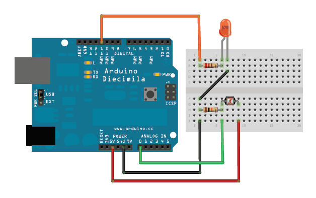
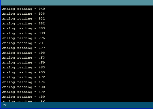
This sketch will take the analog voltage reading and use that to determine how bright the red LED is. The darker it is, the brighter the LED will be! Remember that the LED has to be connected to a PWM pin for this to work, I use pin 11 in this example.
<syntaxhighlight lang="c">
/* Photocell simple testing sketch.
Connect one end of the photocell to 5V, the other end to Analog 0. Then connect one end of a 10K resistor from Analog 0 to ground Connect LED from pin 11 through a resistor to ground For more information see http://learn.adafruit.com/photocells */
int photocellPin = 0; // the cell and 10K pulldown are connected to a0 int photocellReading; // the analog reading from the sensor divider int LEDpin = 11; // connect Red LED to pin 11 (PWM pin) int LEDbrightness; // void setup(void) {
 // We'll send debugging information via the Serial monitor
 Serial.begin(9600);
}
void loop(void) {
 photocellReading = analogRead(photocellPin);

 Serial.print("Analog reading = ");
 Serial.println(photocellReading);     // the raw analog reading

 // LED gets brighter the darker it is at the sensor
 // that means we have to -invert- the reading from 0-1023 back to 1023-0
 photocellReading = 1023 - photocellReading;
 //now we have to map 0-1023 to 0-255 since thats the range analogWrite uses
 LEDbrightness = map(photocellReading, 0, 1023, 0, 255);
 analogWrite(LEDpin, LEDbrightness);

 delay(100);
}
</syntaxhighlight>
You may want to try different pulldown resistors depending on the light level range you want to detect!
