Stepper Motor with Cable
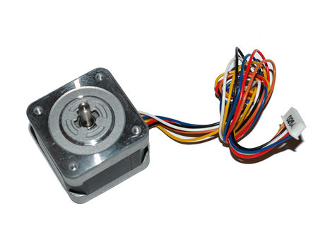
This is a stepper motor with 6-wire and 2-phase.
Contents
Specification
- Step Angle (degrees): 1.8
- 2 phases
- 6-wire cable attached
- Rated current: 1.35A
- Rated voltage: 12V
- Winding resistance: 3.3 Ω
- Size: Length (42mm) x Width (42mm) x Thickness (57mm)
- Diameter of drive shaft (mm): 5m
- Length of drive shaft Length (mm): 23
- Weight: 420 gram
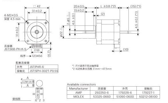
Outline
Wiring Example
6-wire 2-phase stepper motor can be used as 4-wire 2-phase stepper motor if the common wire is not used.
For this stepper motor, Red, yellow, black (com) belong to one group. Blue, brown, white (com) belong to the other group.
The definition of wires is as follows:
- Red: A
- Yellow: B
- Blue:C
- Brown:D
There are two modes of driving:
- 4-beat drive: AC->AD->BD->BC (AC means AC is high level, BD is low level)
- 8-beat drive: A->AC->C->BC->B->BD->D->AD
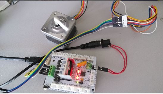
The following shows how to connect the stepper motor to motor shield.
The Arduino sample code is attached.
<syntaxhighlight lang="c"> int pinI1=8;//define I1 interface int pinI2=11;//define I2 interface int speedpinA=9;//enable motor A int pinI3=12;//define I3 interface int pinI4=13;//define I4 interface int speedpinB=10;//enable motor B
- define spead 20 //set stepper motor spead,
- define Beats 4 //select 8 beats or 4 beats
char table[Beats]; void set_beats_number() {
 if(Beats==4)
 {
   table[0] = 0x05;
   table[1] =0x09;
   table[2] =0x0A;
   table[3] =0x06;
 }
 else
 {
   table[0] = 0x01;
   table[1] = 0x05;
   table[2] = 0x04;
   table[3] = 0x06;
   table[4] = 0x02;
   table[5] = 0x0A;
   table[6] = 0x08;
   table[7] = 0x09;
 }
}
void setup() {
 set_beats_number();
 pinMode(pinI1,OUTPUT);
 pinMode(pinI2,OUTPUT);
 pinMode(speedpinA,OUTPUT);
 pinMode(pinI3,OUTPUT);
 pinMode(pinI4,OUTPUT);
 pinMode(speedpinB,OUTPUT);
 digitalWrite(speedpinA,HIGH);
 digitalWrite(speedpinB,HIGH);
}
void beat_control(char beat) {
    digitalWrite(pinI1,beat&0x01);//turn DC Motor B move clockwise
    digitalWrite(pinI2,beat&0x02);
    digitalWrite(pinI3,beat&0x04);//turn DC Motor A move anticlockwise
    digitalWrite(pinI4,beat&0x08);
}
void loop() {
 int i,j;
 for(j=0;j<50;j++)
 {
   for(i=0;i<Beats;i++)
   {
     beat_control(table[i]);
     delay(spead);
   }
 }
 delay(2000);
}
</syntaxhighlight>
Tips
6-wire 2-phase stepper motor has 2 coils. The following is going to explain how to find out the common wire and how the group is divided.
- Use 200ohm of the multimeter.
- Fix one probe of multimeter to one wire, and scan the other probe to other wires, mark the wire showing resistance value (10ohm or 20 ohm). These three wires belong to one group, and noted as R1 and R1.
- If R1=R2, the wire attached to fixed probe is COM.
- If R1=2*R2, the wire that shows resister value for the first time is the COM.
- if R1= 1/2 * R2, the wire that shows resister value for the second time is the COM.
We can use the above method to find out the other coil.


