LED strip driver
Contents
[hide]Introduction
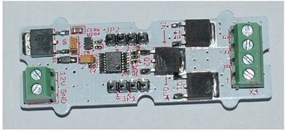
The LED Strip Driver with a 4-pin interface provides easy connectivity to your standard Arduino device.
It can help you control the luminance of a single-color LED strip, as well as the color and the luminance of an RGB LED strip through Arduino.
It has 2 terminals and 2 interfaces. The power for LED strip comes in through the 2-pin terminal. And the LED controlling voltages output through the 4-pin terminal. The 2 interfaces are screen-printed “IN” for controlling data input and “OUT” for controlling data shared with the next strip driver, respectively.
It can drive an LED strip 1 to 2 meters long with 9 V, while 1 to 5 meters long with 12 V. The driver in conjunction with the colorful LED strips can add a wonderful effect to indoor or outdoor usages
Features
- compatible interface (3.3V/5V)
- Can be cascaded for a larger display, with each unit having independent outputs
- Best results achieved with LED strips 5 meters long or shorter
- Outputs PWM signals
- 256 gray-levels are adjustable via programming
- Arduino and MEGA compatible
- Screw Terminals (power input and control signal output interface)
Application Ideas
- Delightful stage light effect
- Indoor light decoration
Cautions
The warnings and wrong operations possible cause dangerous.
Schematic
Specification
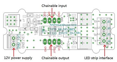
Interface Description
- 12V power supply – Screw terminal for 9-12v power supply.
- Chainable Input – Connected to Arduino or the other driver's chainable output. Pin definition: CLK DIN NC GND.
- Chainable output – Connected to the other driver's chainable input. Pin definition: CLK DOUT NC GND
- LED strip interface – Screw terminals for LED strip. Pin definition: + B R G
Note: VCC of Arduino is not connected to the interface.
Pin definition and Rating
Mechanic Dimensions
Usage
Hardware Installation
Ready To Hardware
- 2 LED Strip Driver boards
- 1 Arduino Duemilanove board
- 1 USB cable
- 6 male and 6 female Dupont wires.
- 1 flat screw driver
- 1 multiple meter
- 12V 1A DC power adaptor
- 1 PC
- 2 2m-long LED strips
How To Set up
- Step 1: Connect power adaptor.
- Connect the 2 LED Strip Driver boards to the DC power adaptor.
- Be cautious about polarity of the power supply even though the driver board has self protection. Do not plug the power adaptor into power outlet yet.
- Step 2: Connect hardware.
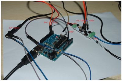
- Connect as following:
- 1. Arduino P2 to Chainable input CLK
- 2. Arduino P3 to DIN
- 3. Ardunio GND to Chainable input GND
- 4. Chainable output CLK to next driver’s Chainable output CLK
- 5. DOUT to next driver’s DIN
- 6. GND to next driver’s GND
- 7. Driver’s “+”、“R”、“G”、“B” to LED strip’s 12V、R、G、B. Be cautious of the polarity and the spec of the LED strips.
- Step 3: Power on.
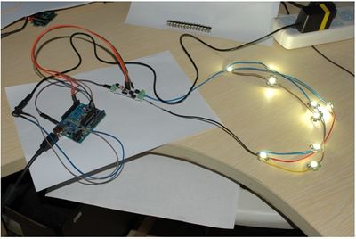
- Plug the DC power adaptor into a power outlet. The LED lights start blinking once a second. Please note that the provided demo code can only control 2 LED strips. The code needs to be revised to control more than 2 LED strips.
Hardware setup of the LED Strip Driver and the LED strips
Programming
- Step 1: Download the LED Strip Driver library here and import it into Arduino-1.0 Libraries: ..\arduino-1.0\libraries.
- Step 2: Run Arduino and open File\Examples\LEDStripDriver\. There are 3 options DemoForWhiteLEDStrip, DualLEDStrip, and SingleLEDStrip.
- Step 3: Select the right Arduino board you are using, like Arduino UNO or Duemilanove or others, and select the right downloading serial port.
- Step 4: Upload the DualLEDStrip demo. Then you can see the alternate colors of red,green,and blue of the LED strip.
FAQ
Please list your question here:
Support
If you have questions or other better design ideas, you can go to our forum to discuss or creat a ticket for your issue at linksprite support.
Resources
How to buy
See Also
Other related products and resources.
Licensing
This documentation is licensed under the Creative Commons Attribution-ShareAlike License 3.0 Source code and libraries are licensed under GPL/LGPL, see source code files for details.


