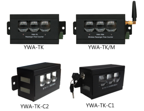
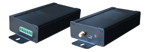
YWA-TK series infrared reflective passenger flow counter
Contents
- 1 Introduction
- 2 Working Principle
- 3 Installation Instructions
- 4 Counting Control (flux switch optional)
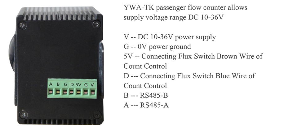
- 5 Interface Specification
- 6 Election Module
- 7 Passenger flow counter clear key instructions (single version)
- 8 Instructions for panel indicator of passenger flow counter
- 9 Installation of Reflector
- 10 Installation Dimension of Passenger Flow Counter
- 11 Main Specifications
- 12 Resources
Introduction
YWA-TK series passenger flow counter is an economical and reliable infrared reflective passenger flow counter with strong anti-light interference ability and anti-vibration ability. Infrared detection distance up to 9 meters, real-time two-way detection, can be used for static statistical places such as shopping malls, but also fo passenger flow statistics in dynamic places such as buses. Since it was put into use in 2002, YWA-TK series passenger flow counter has developed a variety of models and can be customized according to customer needs.
Working Principle
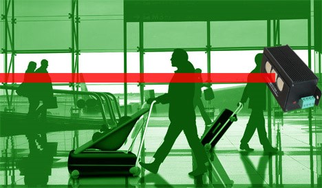
The YWA-TK passenger flow counter is designed with infrared transceiver. The infrared beam emitted by the passenger flow counter is received by the two receivers inside the passenger flow counter through the matching reflector. When the pedestrians pass through, the infrared beam is occluded. The passenger flow counter obtains the pedestrian direction information through the detection of the sequence of the infrared beam occlusion, and produces a passenger flow data with direction information, and exchange data with the third party device through the communication interface.
The stand-alone version (such as YWA-TK-C) passenger flow counter is displayed on the LCD display according to the flow counters in different directions. The LCD display shows the accumulated passenger flow data, that is, the total number of passenger flows since the last data was cleared. It will not be lost because the device is powered off, unless it is cleared with the matching key.
Installation Instructions
The YWA-TK passenger flow counter is installed at a height of 1.3-1.4m from the ground at the entrance and exit for level detection. When the customer passes, the carry-on baggage (handbag, suitcase, etc.) is not detected by the passenger flow counter, so it will not be counted repeatedly. The infrared beam of the YWA-TK passenger flow counter can penetrate the glass, but the glass tilt angle cannot be greater than 15 degrees. The reflector board is positioned in front of YWA-TK passenger flow counter, the longest distance is 9 meters, It is located on the same horizontal plane as YWA-TK passenger flow counter, for reflecting the infrared beam from the YWA-TK passenger counter.
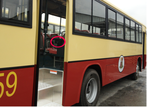
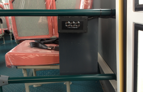
When the YWA-TK passenger flow counter is used in the bus, it should be installed on the right side of the direction of getting on the bus door and placed horizontally with a height of 1.1-1.2m from the pedal.
The installation position of YWA-TK passenger flow counter should be firm and not affect passenger traffic.
Counting Control (flux switch optional)
The counting control function is used to filter the counting generated by the movement of objects which are not statistical objects, such as doors or curtains. If the installation position of YWA-TK passenger flow counter is disturbed by the movement of doors or curtains, a flux switch is needed for counting control.
The YWA-TK passenger flow counter used on bus is usually installed within the range of the door activity due to the limited installation position. The door movement process when the door is opened or closed may block the infrared beam of YWA-TK passenger flow counter, resulting in unnecessary counting. The interference during the door movement process can be filtered by using counting control.
Taking the bus service environment as an example, the flux switch is installed at the door frame, and the matching magnet is adsorbed on the movable door leaf. When the door is opened, the distance between the magnet and the flux switch is no more than 2cm. At this time, the indicator light of the flux switch lights up, and the YWA-TK passenger flow counter starts to count. When the door is closed, the indicator light of the magnetic flux switch will be off when the magnet leaves the flux switch more than 2cm, and the YWA-TK passenger flow counter will stop counting.
Interface Specification
Election Module
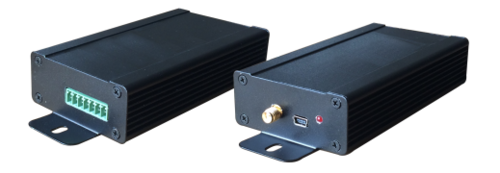
The YWA-TK passenger flow counter transmits data with other devices (such as communication with computer or communication with car GPS device to realize data remote transmission) via RS485 (or custom RS232), and can also use matching modules to form a complete passenger flow counting system to use independently.
a. SD Storage Module
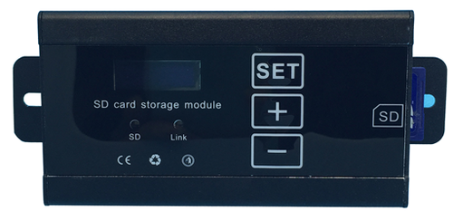
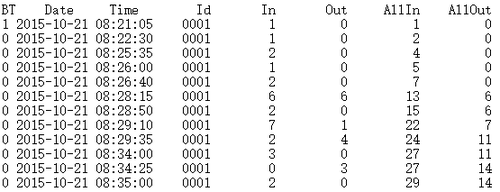
The module is suitable for bus environment. The number of passenger flow and corresponding time collected by each door of the bus are automatically stored in SD card, and the data can be stored for a maximum of 6 months continuously. The SD card produces a TXT file every day, which records the detailed flow of passengers on that day.
b. ZIG Wireless Communication Module
This module is suitable for the bus. The total number of passengers per day can be automatically uploaded to the fleet designated computer or cloud server when the bus enters the fleet parking lot. And the daily passenger records of each car can be viewed through the WEB report system.
c. WIFI Module
The module is suitable for use in a bus environment with a network. When the bus enters the WIFI network coverage, the statistics will be automatically uploaded to the cloud server, and the detailed passenger flow record of each bus will be viewed through the WEB reporting system.
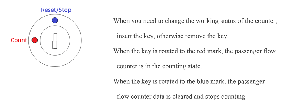
Passenger flow counter clear key instructions (single version)
Instructions for panel indicator of passenger flow counter
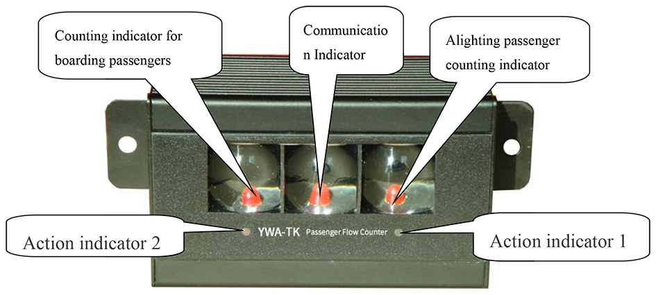
There are 5 indicators on the YWA-TK passenger flow counter panel, 3 of which are behind the glass lens. Action indicator 1 and action indicator 2 is used to display the range of installation position of the reflector. When the reflector is not installed after the YWA-TK passenger flow counter is powered on, the action indicator 1 and the action indicator 2 are always on. When the reflector is within the detection range of the passenger flow counter, the action indicator 1 and the action indicator 2 are off.
When the YWA-TK passenger flow counter +1 passenger, the passenger count light flashes once. and when a passenger exit the exit light flashes once. The communication light flashes when the devcice exchanging the data with third-party device.
Installation of Reflector
Ensure that there is no obstruction between the passenger flow counter and the reflector during installation, and the maximum distance between the reflector and the counter should not exceed 10m. On the other side of the entrance and exit, the reflector is placed horizontally towards the passenger flow counter. Look for a position where both action indicators can be turned off, and the installation location can be confirmed by simulating pedestrians in and out.
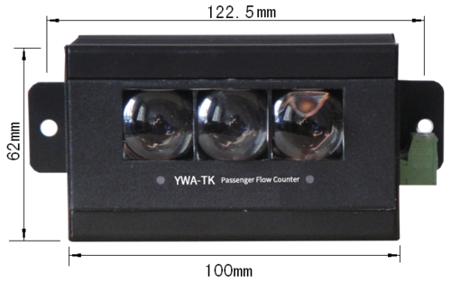
Installation Dimension of Passenger Flow Counter
Main Specifications
1.Number of maximum digits: 99999999
2.Maximum infrared reflection distance: 9m
3.Anti-vibration ability: amplitude 0.35mm, 60-200Hz, acceleration 50m / s2
4.Temperature range: -20 ~ +65 ° C
5.Working voltage: DC 9-36V, voltage fluctuation 15%
6.Working current: less than 50mA
7.Infrared scanning frequency 1KHz
8.Infrared wavelength: 850um
9.Anti-light interference ability: 1000Lux

