Serial UART 16x2 LCD
Contents
Introduction
The serial UART 16x2 LCD allows you to control a parallel based LCD over a single-wire serial interface. The serial LCD takes care of all the HD44780 commands allowing seamless integration with any micro that can communicate over a wide range of TTL serial baud rates. The
Communication with Serial 16x2 LCD requires 5V TTL serial at a default baud rate of 9600bps (8-N-1). You can adjust the baud to any standard rate between 2400 and 38400bps. The power, ground and RX pins are all broken out to a 4-pin 2.54mm pitch header.
Serial 16x2 LCD has the ability to dim the backlight to conserve power if needed. There is also a potentiometer on the backpack to adjust the contrast.
Features
- Embedded PIC 16F88 utilizes onboard UART for greater communication accuracy
- Baud rates of 9600
- Greater processing speed at 10MHz
- Incoming buffer stores up to 80 characters
- Backlight transistor can handle up to 1A
- Pulse width modulation of backlight allows direct control of backlight brightness and current consumption
- All surface mount design allows a backpack that is half the size of the original
- Faster boot-up time
- Boot-up display can be turned on/off via firmware
Application Ideas
Cautions
Schematic
Specification
| Item | Min | Typical | Max | Unit |
|---|---|---|---|---|
| Voltage | 3.5 | 5 | 5.5 | V |
| Current | 120 | 210 | 350 | mA |
| Maximum Communication Distance | 5 | cm | ||
| Dimension | 72.6x58.4x23.2 | mm | ||
| Supported Card Type | Mifare One | / | ||
| Net Weight | 24.2 | g | ||
Pin definition and Rating
Mechanic Dimensions
Usage
Hardware Installation
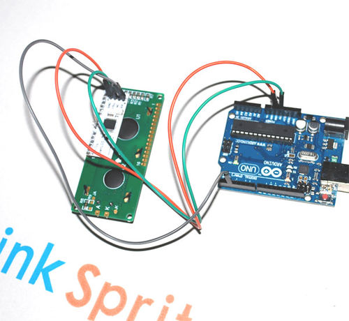
- Connect the 5V of Serial LCD to 5V on Arduino.
- Connect GND of Serial LCD to GND of Arduino.
- Connect RX of Serial LCD to digital 3 of Arduino.
Programming
The following is the sample code assuming that the RX of serial LCD is connected to digital 2 of Arduino. The following code has been tested on Arduino IDE 1.0.1.
<syntaxhighlight lang="c">
- include <SoftwareSerial.h>
- define txPin 2
SoftwareSerial LCD = SoftwareSerial(0, txPin); // since the LCD does not send data back to the Arduino, we should only define the txPin const int LCDdelay=10; // conservative, 2 actually works
// wbp: goto with row & column void lcdPosition(int row, int col) {
 LCD.write(0xFE);   //command flag
 LCD.write((col + row*64 + 128));    //position
 delay(LCDdelay);
} void clearLCD(){
 LCD.write(0xFE);   //command flag
 LCD.write(0x01);   //clear command.
 delay(LCDdelay);
} void backlightOn() { //turns on the backlight
 LCD.write(0x7C);   //command flag for backlight stuff
 LCD.write(157);    //light level.
 delay(LCDdelay);
} void backlightOff(){ //turns off the backlight
 LCD.write(0x7C);   //command flag for backlight stuff
 LCD.write(128);     //light level for off.
  delay(LCDdelay);
} void serCommand(){ //a general function to call the command flag for issuing all other commands
LCD.write(0xFE);
}
void setup() {
 pinMode(txPin, OUTPUT);
 LCD.begin(9600);
 backlightOn() ;
 clearLCD();
 lcdPosition(0,0);
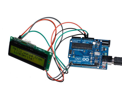
 LCD.print("Hello world from LinkSprite!");
}
void loop() { }
</syntaxhighlight>
FAQ
Please list your question here:
Support
If you have questions or other better design ideas, you can go to our forum to discuss or creat a ticket for your issue at linksprite support.
Resources
How to buy
See Also
Other related products and resources.
Licensing
This documentation is licensed under the Creative Commons Attribution-ShareAlike License 3.0 Source code and libraries are licensed under GPL/LGPL, see source code files for details.

