Linker kit Base Shield for Raspberry Pi with ADC Interface
Contents
Description
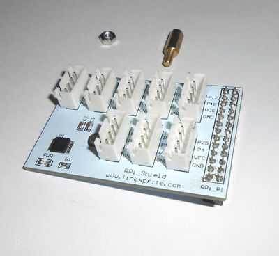
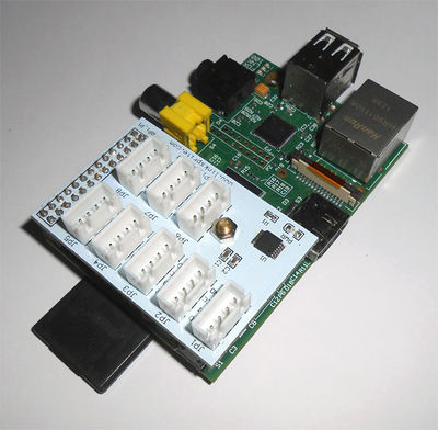
This is a Linker kit base shield for Raspberry Pi with ADC interface. All the Linker kit modules can be plugged onto Raspberry Pi through this base shield. Moreover, this shield has an on-board ADC chip so that analog output modules can be used on Raspberry Pi. The ADC chip used is MCP3004. It talks to Raspberry Pi using SPI interface.
Specification
There are 8 4-pin 2.54mm spacing housing on the base shield:
- JP1: A0, A1, VCC, GND.
- JP2: A2, A3, VCC, GND.
- JP3: SCL, SDA, VCC, GND.
- JP4: RXD, TXD, VCC, GND.
- JP5: P17, P18, VCC, GND.
- JP6: P27, P22, VCC, GND.
- JP7: P23, P24, VCC, GND.
- JP8: P24, P4, VCC, GND.
These connectors cover Analog, I2C, and GPIO.
Install Base Shield on Raspberry Pi
Schematics
Tutorial
The ADC chip used on this base shield is MCP3004 (10 bit resolution, 4 channels, SPI interface). In the following, we are going to cover how to use Python to read the ADC output:
As we use SPI communication, we need to enable SPI module in kernel. To do that, we can edit the blacklist of kernel, and enable spi:
sudo vi /etc/modprobe.d/raspi-blacklist.conf
Locate the line begins with "blacklist spi-bcm2708" and change it to "#blacklist spi-bcm2708".
After this, we can check the module by "lsmod", and observe the following content:
Module                  Size  Used by
spi_bcm2708             4421  0

