LED Bar
Introduction
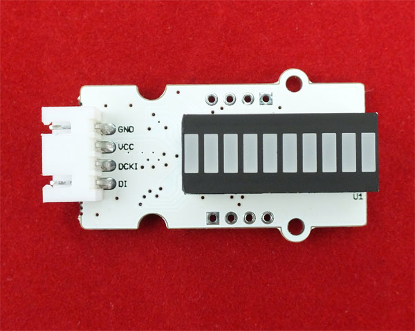
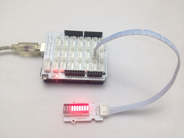
This is a LED bar with Linker kit standard connection.
Schematics
Application Ideas
<syntaxhighlight lang="c">
- define PORT_Data PORTB
- define PORT_Clk PORTB
- define DATA_Pin 8 //DATA IN
- define CLK_Pin 9 //CLK IN
- define BIT_Data 0x01
- define BIT_Clk 0x02
- define CmdMode 0x0000 //Work on 8-bit mode
- define ON 0x00ff //8-bit 1 data
- define SHUT 0x0000 //8-bit 0 data
//Send 16_bit data void send16bitData(unsigned int data) {
 for(unsigned char i=0;i<16;i++)
   {
       if(data&0x8000)
       {
           PORT_Data |= BIT_Data;
       }
       else
       {
           PORT_Data &=~ BIT_Data;
       }
       PORT_Clk ^= BIT_Clk;
       data <<= 1;
   }
}
//latch routine for MY9221 data exchange void latchData(void) {
   PORT_Data &=~ BIT_Data;
   delayMicroseconds(10);
   for(unsigned char i=0;i<8;i++)
   {
       PORT_Data ^= BIT_Data;
   }
}
//Initializing pins void setup() {
 pinMode(DATA_Pin,OUTPUT);  //Data pin
 pinMode(CLK_Pin,OUTPUT);  //CLK pin
}
//Send 12 road led brightness data void sendLED(unsigned int LEDstate) {
 unsigned char i;
 for(i=0;i<12;i++)
 {
   if(LEDstate&0x0001)
     send16bitData(ON);
   else
     send16bitData(SHUT);
// if(i!=11)
     LEDstate=LEDstate>>1;
 }
}
//If you want turn on the first red led,you can do it like this: sendLED(0x0001); //The second led: sendLED(0x0002); void loop() {
 unsigned int i=0x0000;
 while(i<=0x03ff)
 {
   send16bitData(CmdMode);  //set first LED Bar mode
   sendLED(i);  //send first LED Bar data
   send16bitData(CmdMode);  //set second LED Bar mode,if you do not use two LED Bar work together(connect one by one),you can delete this line.
   sendLED(i);  //send second LED Bar data,if you do not use two LED Bar work together(connect one by one),you can delete this line.
   latchData();  //make it come into effect
   i=i*2+1;
  delay(100);
 }
} </syntaxhighlight>
Sample Code
How to buy
Here to buy LED Bar on store

