Hall Effect Sensor
Hall effect sensors detect whether a magnet is near. Useful for non-contact/waterproof type switches, position sensors, rotary/shaft encoders.
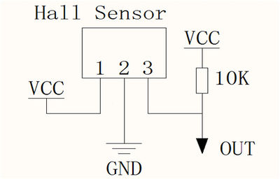
Runs at 3.5V up to 24V. To use connect power to pin 1 (all the way to the left), ground to pin 2 (middle) and then a 10K pull up resistor from pin 3 to power. Then listen on pin 3, when the south pole of a magnet is near the front of the sensor, pin 3 will go down to 0V. Otherwise it will stay at whatever the pullup resistor is connected to. Nothing occurs if a magnet's north pole is nearby (unipolar).
Example Project
The purpose of this project is to demo the usage of Hall Sensor. When the magnet is close to Hall sensor, the LED-L on Arduino will turn on, and the LED will turn on when the magnet is removed.
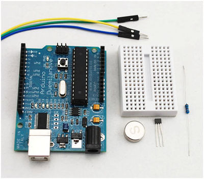
List of Components:
| Item | Quantity |
|---|---|
| Arduino Duemilanove or Uno | 1 |
| Hall Sensor | 1 |
| USB Cable with type A Interface | 1 |
| Mini Breadboard | 1 |
| Jumper Wire with Male Header | 3 |
| Resister with value 10K ohm | 1 |
| PC | 1 |
Schematics:
Hardware:
Components needed for the project
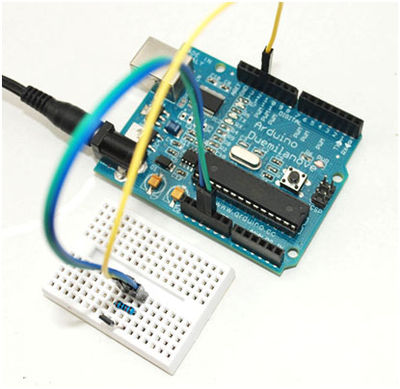
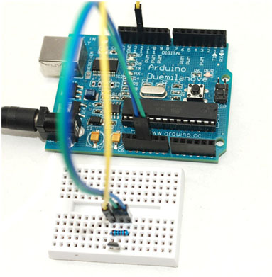
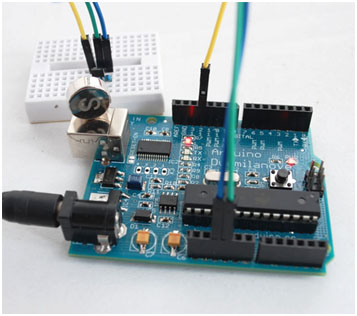
Wiring Picture
When there is no magnet close to the Hall sensor, the LED-L will remain off.
When magnet is close to the Hall sensor, the LED-L will turn off.
Pin 3 of hall sensor is connected to D12. D12 will detect the voltage level of D12 to judge if there is magnet close to it. The result will be displayed on LED-L which is controlled by D13.
Code:
<syntaxhighlight lang="c">
int ledPin = 13; int out = 12;
void setup() {
  pinMode(ledPin, OUTPUT);
  pinMode(out, INPUT);
}
void loop() {
if ( digitalRead(out) )
{
digitalWrite(ledPin,LOW );
}
else
{
digitalWrite(ledPin,HIGH);
} }
</syntaxhighlight>
