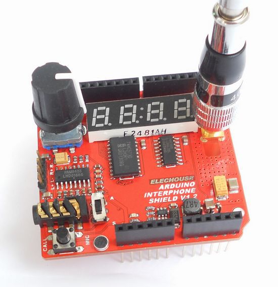
Wireless Intercom Walkie-Talkie Shield for Arduino/pcDuino
Contents
Description
- Serial/UART interface control
- Frequency Range: 400 ~ 470MHZ;
- Frequency step: 5K/6.25K/12.5K/25K
- RF power output: 1W (High power) or 0.5W (low power)
- Voice encryption
- Send and receive SMS text message
- Built-in CTCSS (38 groups), CDCSS (83 groups) codec
- Squelch Level (0-9 grade) adjustable
- High receiver sensitivity:-122dBm
- Ultra-low-power sleep mode (0.1uA)
- Voltage operating range: 7 ~ 20V
There is an external MIC on the board. It works while the earphone jack is unloaded. If the earphone is plugged in, the external MIC is disabled. Note that the earphone jack has 4 poles. So use could plug in earphone with Mic such iPhone's or Samsung smartphone's. As earphones from Apple and Samsung are different, the earphone switch was added to make it compatible with both. While the earphone is unloaded, you could also manual disable external MIC by setting the earphone switch to A.
If necessary, a speaker could be connected to the 4-pin header. There is a 2 channel 3W amplifier chip on the board. And the 4pin header is the output of the amplifier.
There is a switch on the board to setting the consumption. That means, it would affect the working distance. By default, the setting is HIGH (you don't have to bridge right two). By bridging the left 2 pins (L pin and the middle pin), the power consumption is lower. And the working distance is around 530m.
Arduino sends command to this module through serial/UART interface. This module has two soldering switches on the back. It could jump the UART pin between (pin 0, pin 1) and (pin 2, pin 3). Pin 0 and pin 1 are hardware serial port of Arduino, which is also used to upload sketch to Arduino. By default we set it to (pin2, pin 3). SoftSerial library could be used for serial communication.
The device would draw large current. So the Arduino might get hot.
The module is designed for Arduino UNO/Duemilanove. You only need to plug in and play.
Steps
- Upload sample code to two Arduino with interphone modules.
- Mount the antenna and plug in earphone with MIC
- Power on Arduino
- Turn the frequency turners of the two to the same frequency
Software
- Download interphone library( git clone git://github.com/elechouse/interphone.git or download zip package ).
- Copy interphone folder to arduino_dir/libraries or arduino/schetchbook/dir/libraries.
- open or restart your Arduino IDE if it is opened.
- open interphone_test from File->Examples->interphone>interphone_test
- upload interphone_test to you Arduino board.
- push the CALL button to talk.
