3G + GPS Shield for Arduino
Contents
Introduction
The new 3G shield for Arduino enables the connectivity to high speed WCDMA and HSPA cellular networks in order to make possible the creation of the next level of worldwide interactivity projects inside the new "Internet of Things" era.
The module counts also with an internal GPS what enables the location of the device outdoors and indoors combining standard NMEA frames with mobile cell ID triangulation using both assisted-mobile (A-GPS) and mobile-based (S-GPS) modes.
Other interesting accessories which can be connected to the module are a video camera which enables the record of video in high resolution (640x480), an audio kit including microphone, speaker, hands free and headphones sets and a SD socket to save directly all the data coming from the 3G network or recorded from the video camera. You can even reproduce audio files stored in the SD card (like a mp3 player!).
You can also use it as a standard 3G modem at full speed (~7.2Mbps download, ~5.5Mbps upload) just connecting it through its specific mini-USB socket to your laptop (Linux, Windows, MacOS).
The new communicating module is specially oriented to work with Internet servers implementing internally several application layer protocols which make easier to send the information to the cloud. We can make HTTP and HTTPS (secure mode) navigation, downloading and uploading content to a web server. In the same way FTP and FTPS (secure mode) protocols are also available which is really useful when your application requires handling files. You can even send and receive mails directly from Arduino using the SMTP and POP3 clients implemented internally.
With the SD Card socket so you can handle a complete FAT16 file systems and store up to 32GB of information. This specially useful as the 3G module can work at full speed (~7.2Mbps download, ~5.5Mbps upload) when working with the SD files directly without need of Arduino for data or files management.
The GPS module also makes possible perform geolocation services even in indoors as it can work in A-GPS and S-GPS modes, so the location given by the GPS through NMEA sentences is completed with the cell information provided by both the 3G module and external Internet Geoposition Servers which helps you to get the most accurate location in each case.
Features
- WCDMA and HSPA 3G networks compatibility
- Internal GPS for Assisted A-GPS and Supported S-GPS modes
- Video Camera (640x480) for video and photo recordings available
- Audio Kit including microphone, speaker, hands free and headphones available
- SD file system up to 32GB
- Works as a standard 3G modem in Linux/Windows/MacOS (~7.2Mbps download, ~5.5Mbps upload)
- Talk directly to web servers by HTTP/HTTPS (secure)
- Upload and download files directly by FTP/FTPS (secure)
- Send and receive mails by POP3/SMTP
- Play compressed audio files
Antennas
Connections
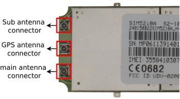
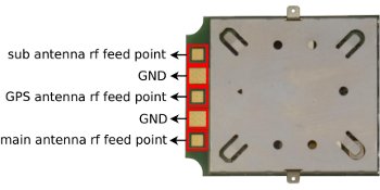
SIM5218 has 3 UFL connectors. Two for diversity of 3G mobile carriers and one for GPS antenna. The impedance of the RF interface is 50Ω. It is recommended use just the "main" antenna socket for the mobile connection unless you experience coverage or performance problems. In this case two antennas allowing diversity may be placed.
Also, the module allows to solder the antenna to the pad, or attach it via contact springs.
Bandwidth
3G module connected with Arduino allows downlinks rates over 115200 bauds (~11.5KBps), the maximum UART's speed and uplinks rates over 30000 bauds (~3KBps).
Using the module as 3G USB modem we got speeds of 2Mbps (~222KBps) for downlink and 0.7Mbps (~77KBps) for uplink and.
The connection speed may vary depending on the state of the network, the quality of the signal and the carrier.
Using 3G module with AT commands
Important issues:
- Use capital letters for AT commands.
- Send CR (Carriage return) and LF (Line feed) after the AT command.
- Place the serial communication jumpers in the right position.
- Use an external power supply and place the power jumpers in the right position. If the shield is powered from the Arduino, the power jumper must be in Arduino 5V position. If the shield is powered from the Vin input (in the shield), the power jumper must be in Vext position.
The first thing we are going to do with the module is to connect the module to a PC directly (using an Arduino as gateway) and check the basic AT commands. In this case, serial communication jumpers have to be set on USB gateway position.
Remember take out the ATmega microcontroller from the Arduino gateway.
Basic configuration:
Connect the shield to the Arduino gateway.
Then connect the SIM card and the USB cable.
Finally plug the USB cable to the computer and open a serial port terminal to communicate via the usb port (e.g: hyperterminal (win), cutecom / gtkterm (linux)).
If you use the Arduino IDE serial monitor for sending AT commands – Be sure that you are sending CR (Carriage return) and LF (Line Feed).
Set the baudrate to 115200 bps and open the serial port, then press the ON button for two seconds. Then if you type AT you'll get OK, this means that the communication with the module is working fine. Now, with the module working you can check some AT commands to control the module, the basic commands are:
Important type commands in capital letters and with CR (carriage return) and LF (line feed)!!!
| Command | Respone | Description |
|---|---|---|
| AT | OK | If you get OK, the communication with the module is working |
| AT+CPIN="****" | OK | If the SIM card is locked with PIN (**** is the pin number) |
| AT+COPS? | Operator information |
NOTE: If your 3G module doesn't answer to AT commands, maybe it is configured in a different baudrate. The command for change it temporally is AT+IPR. Try differents baudrates (300, 600, 1200, 2400, 4800, 9600, 19200, 38400, 57600, 115200, 230400, 460800,921600, 3200000,3686400,4000000 ) until you get to communicate. Once you can communicate, you can configure it in the baudrate you want.
Using 3G module like a modem
If you want to use the 3G module such a modem, please refer to the next link:
[3G modem tutorial]
Audio
Audio Features
SIM5218 module provides two analogy inputs for microphone and three analogy outputs for two speakers and headphones. Depending of the selected audio channel (normal, headset and hands-free) a specific input and output are activated. The different channels are selected with the command AT+CSDVC.
Normal channel (AT+CSDVC=1) uses the main microphone and a speaker. Headset channel (AT+CSDVC=2) uses the jack connector. Hand-free channel (AT+CSDVC=3) uses the main microphone and the loudspeaker.
Both microphones don't need an external power source because they are powered directly by the module. You can use some extra commands in your codes like noise suppression, echo canceller or the gain of the mic amps. Please, refer to the AT command document list at the end of this article for more information.
Audio Connectors
Audio connectors are situated at the bottom of the board. The two speakers and the main microphone are connected to board using pin connectors.
Headset connector are situated at the bottom too, between Arduino board and 3G board.
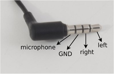
This connector has 4 terminals that correspond with the positive terminal of the microphone, left and rigth headphones and common ground. The order of connections show below.
Originating and receiving voice calls
The code example and the connection diagram shown below are used to originate a voice call and, pushing a button, end that voice call. The button is connected between digital pin 12 an ground. A 10kΩ pull-up resistor is needed at this pin.
<syntaxhighlight lang="c"> /*
- This program is free software: you can redistribute it and/or modify
- it under the terms of the GNU General Public License as published by
- the Free Software Foundation, either version 3 of the License, or
- (at your option) any later version.
- This program is distributed in the hope that it will be useful,
- but WITHOUT ANY WARRANTY; without even the implied warranty of
- MERCHANTABILITY or FITNESS FOR A PARTICULAR PURPOSE. See the
- GNU General Public License for more details.
- You should have received a copy of the GNU General Public License
- along with this program. If not, see .
- Version 0.1
- Author: Alejandro Gállego
- /
int led = 13;
int button = 12;
int onModulePin = 2; // the pin to switch on the module (without press on button)
int timesToSend = 1; // Numbers of calls to make
char phone_number[]="*********"; // ********* is the number to call
void switchModule(){
   digitalWrite(onModulePin,HIGH);
   delay(2000);
   digitalWrite(onModulePin,LOW);
}
void setup(){
   Serial.begin(115200);                // UART baud rate
   delay(2000);
   pinMode(button, INPUT);
   pinMode(led, OUTPUT);
   pinMode(onModulePin, OUTPUT);
   switchModule();                    // switches the module ON
   for (int i=0;i < 5;i++){
       delay(5000);
   }
}
void loop(){
while (count < timesToSend){
       for(int x=0;x < 9;x++){        //generates the tones of the phone number
           Serial.print("AT+CPTONE=");
           Serial.println(phone_number[x]);
           delay(400);
       }
       Serial.print("ATD");
       Serial.print(phone_number);
       Serial.println(";");
while(digitalRead(button)==1);
Serial.println("AT+CHUP"); // disconnects the existing call
delay(5000);
       count++;
   }
}
</syntaxhighlight>
To make a lost call next code is used.
<syntaxhighlight lang="c"> /*
- This program is free software: you can redistribute it and/or modify
- it under the terms of the GNU General Public License as published by
- the Free Software Foundation, either version 3 of the License, or
- (at your option) any later version.
- This program is distributed in the hope that it will be useful,
- but WITHOUT ANY WARRANTY; without even the implied warranty of
- MERCHANTABILITY or FITNESS FOR A PARTICULAR PURPOSE. See the
- GNU General Public License for more details.
- You should have received a copy of the GNU General Public License
- along with this program. If not, see .
- Version 0.1
- Author: Alejandro Gállego
- /
int led = 13;
int onModulePin = 2; // the pin to switch on the module (without press on button)
int timesToSend = 1; // Numbers of calls to make int count = 0; int tones = 2; //Each tone has a duration of 6 seconds aprox.
char phone_number[]="*********"; // ********* is the number to call
void switchModule(){
   digitalWrite(onModulePin,HIGH);
   delay(2000);
   digitalWrite(onModulePin,LOW);
}
void setup(){
   Serial.begin(115200);                // UART baud rate
   delay(2000);
   pinMode(led, OUTPUT);
   pinMode(onModulePin, OUTPUT);
   switchModule();                    // switches the module ON
   for (int i=0;i < 5;i++){
       delay(5000);
   }
}
void loop(){
   while (count < timesToSend){
       delay(1500);
   for(int x=0;x < 9;x++){        //generates the tones of the phone number
           Serial.print("AT+CPTONE=");
           Serial.println(phone_number[x]);
           delay(400);
       }
       Serial.print("ATD");
       Serial.print(phone_number);
       Serial.println(";");
       delay(6000*tones);
       Serial.println("AT+CHUP");            // cancel the call
delay(5000);
       count++;
   }
} </syntaxhighlight>
To receive calls the used code are this and the connection diagram is the same that the used to originate calls. Don't forget the pull-up resistor on pin 12.
<syntaxhighlight lang="c"> /*
- This program is free software: you can redistribute it and/or modify
- it under the terms of the GNU General Public License as published by
- the Free Software Foundation, either version 3 of the License, or
- (at your option) any later version.
- This program is distributed in the hope that it will be useful,
- but WITHOUT ANY WARRANTY; without even the implied warranty of
- MERCHANTABILITY or FITNESS FOR A PARTICULAR PURPOSE. See the
- GNU General Public License for more details.
- You should have received a copy of the GNU General Public License
- along with this program. If not, see .
- Version 0.1
- Author: Alejandro Gállego
- /
int led = 13;
int button = 12;
int onModulePin = 2; // the pin to switch on the module (without press on button)
int timesToSend = 1; // Numbers of calls to make
void switchModule(){
   digitalWrite(onModulePin,HIGH);
   delay(2000);
   digitalWrite(onModulePin,LOW);
}
boolean check_response(char *str){
   int i = 0;
   int j = 0;
   char b[10];
   // reading the message and cutting
   // initials and finals
   while(Serial.available() > 0){
       if(j==0 || j==1){
           Serial.read();
           j++;
       }
       else if( Serial.peek() == 13 ){
           b[i] = 0;
           Serial.read();
       }
       else if( Serial.peek() == 10 ){
           Serial.read();
       }
       else {
           b[i++] = Serial.read();
       }
   }
   // comparing
   int cont=0;
   int cont2=0;
   boolean ok=false;
   while(b[cont]!=-1){
       if (b[cont]==str[cont2]){
           while(str[cont2]!=-1){
               if (b[cont+cont2]!=b[cont2])
               {
                   cont2++;
                   ok=true;
               }
               else {
                   ok=false;
                   break;
               }
           }
       }
       if (ok) break;
       cont++;
   }
   if(ok){
       return true;
   }

   return false;
}
void setup(){
   Serial.begin(115200);                // UART baud rate
   delay(2000);
   pinMode(button, INPUT);
   pinMode(led, OUTPUT);
   pinMode(onModulePin, OUTPUT);
   switchModule();                    // switches the module ON
   for (int i=0;i < 5;i++){
       delay(5000);
   }
}
void loop(){
   while(!check_response("RING"));   //waits for a call
   Serial.println("ATA");          //answers an incoming call
   delay(10000);

   while(digitalRead(button)==1);
Serial.println("AT+CHUP"); // disconnects the existing call
} </syntaxhighlight>
The channel may be changed during a call. Use the command AT+CSDVC to select the channel that you want.
Recording and playing sound
With the next code we can record a sound, stores it and before play it. You can select the place to store the sound clip: the local storage or a SD card. Once saved the sound can be sent to an FTP or FTPS as you'll see later.
<syntaxhighlight lang="c"> /*
- This program is free software: you can redistribute it and/or modify
- it under the terms of the GNU General Public License as published by
- the Free Software Foundation, either version 3 of the License, or
- (at your option) any later version.
- This program is distributed in the hope that it will be useful,
- but WITHOUT ANY WARRANTY; without even the implied warranty of
- MERCHANTABILITY or FITNESS FOR A PARTICULAR PURPOSE. See the
- GNU General Public License for more details.
- You should have received a copy of the GNU General Public License
- along with this program. If not, see .
- Version 0.1
- Author: Alejandro Gállego
- /
int led = 13;
int onModulePin = 2; // the pin to switch on the module (without press on button)
int x = 0;
char name[20];
void switchModule(){
   digitalWrite(onModulePin,HIGH);
   delay(2000);
   digitalWrite(onModulePin,LOW);
}
void setup(){
   for(x=0;x < 20;x++){
       name[x]='\0';
   }
   Serial.begin(115200);                // UART baud rate
   delay(2000);
   pinMode(led, OUTPUT);
   pinMode(onModulePin, OUTPUT);
   switchModule();                    // switches the module ON
   for (int i=0;i < 5;i++){
       delay(5000);
   }

   Serial.println("AT+FSLOCA=0");
   // store media files to local storage space, put 1 to store media files to storage card
   while(Serial.read()!='K');

   Serial.println("AT+CNSM=1");     // Enables noise supression
   while(Serial.read()!='K');
}
void loop(){
   //RECORDING A SOUND CLIP
   delay(1500);
   while(Serial.available()!=0){
       Serial.read();
   }
   Serial.println("AT+CQCPREC=0,amr");     // starts to record a sound clip
   Serial.flush();
   while(Serial.read()!='/');
   while(Serial.read()!='/');
   x=0;
   do{
       while(Serial.available()==0);
       name[x]=Serial.read();
       x++;
   }while(x < 19);
   while(Serial.read()!='K');
   Serial.println(name);
   delay(10000);
   Serial.println("AT+CQCPPAUSE");     // pauses record sound
   while(Serial.read()!='K');
   delay(2000);
   Serial.println("AT+CQCPRESUME");     // resumes record sound
   while(Serial.read()!='K');
   delay(10000);
   Serial.println("AT+CQCPSTOP");     // stops to record a sound clip
   while(Serial.read()!='K');
   //PLAY A SOUND CLIP
   Serial.println("AT+FSCD=Audio");
   Serial.flush();
   while(Serial.read()!='K');
   Serial.print("AT+CCMXPLAY=\"");    //plays an audio file
   Serial.print(name);
   Serial.println("\"");
   Serial.flush();
   while(Serial.read()!='K');
   delay(7000);
   Serial.println("AT+CCMXPAUSE");     // pauses playing audio file
   while(Serial.read()!='K');
   delay(2000);
   Serial.println("AT+CCMXRESUME");     // resumes playing audio file
   while(Serial.read()!='K');
   delay(8000);
   Serial.println("AT+CCMXSTOP");     // Stops playing audio file
   while(Serial.read()!='K');
while(1);
} </syntaxhighlight>
Also, you can use the 3G module like a mp3 player! First, you must save your music in mp3, amr or qcp format. You can use Audacity (linux) or Mobile Media Converter (Windows or Linux) to do this. Then, save the music in the Audio folder on microSD card. Now, put microSD card into the shield and enjoy the music!
NOTE: You will need to update your firmware to play mp3. The update is available here. Uncompress and run it in a PC with Windows (emulated Windows not supported).
A voice call can be recorded using these same commands too.
Command summary
| Command | Response | Description |
|---|---|---|
| AT+CPTONE=** | OK | Plays a DTMF tone or complex tone on local voice channel device . ** is the number of the tone. |
| ATD*********; | ********* is the number to call. |


