DIY CNC 3 Axis Engraver Machine PCB Milling Wood Carving Router Kit Arduino Grbl
Contents
Introduction
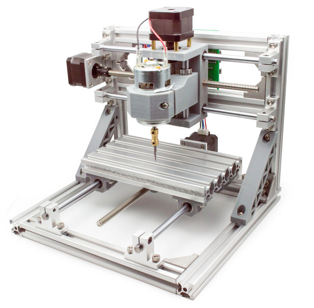
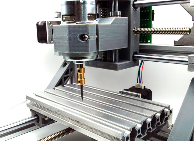
The mini CNC engraving machine laser engraving machine is suit for make non- metal processing such as plastic , wood , acrylic , pvc, pcb, wood or the like material , etc.And airframe adopt profiles + plastic ,small size, light weight , USB interface , open source GRBL control.
Grbl is a no-compromise, high performance, low cost alternative to parallel-port-based motion control for CNC milling. It will run on a vanilla Arduino (Duemillanove/Uno) as long as it sports an Atmega 328.
The controller is written in highly optimized C utilizing every clever feature of the AVR-chips to achieve precise timing and asynchronous operation. It is able to maintain up to 30kHz of stable, jitter free control pulses.
It accepts standards-compliant g-code and has been tested with the output of several CAM tools with no problems. Arcs, circles and helical motion are fully supported, as well as, all other primary g-code commands. Macro functions, variables, and most canned cycles are not supported, but we think GUIs can do a much better job at translating them into straight g-code anyhow.
Grbl includes full acceleration management with look ahead. That means the controller will look up to 18 motions into the future and plan its velocities ahead to deliver smooth acceleration and jerk-free cornering.
Usage
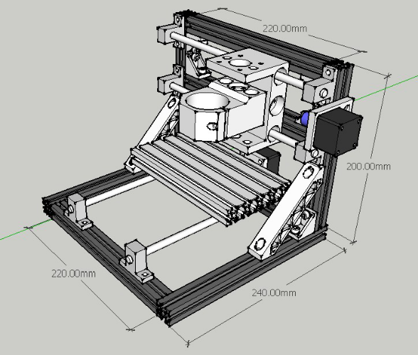
Model profile size
Assemble instruction
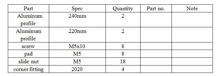
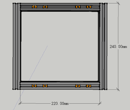
1.Pedestal Assemble
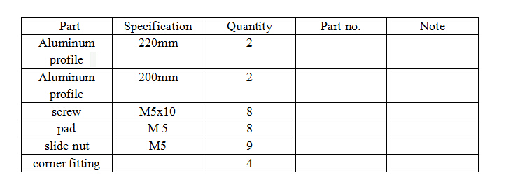
a)Part:
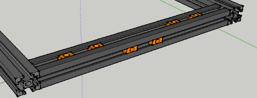
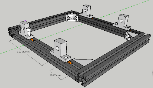
b)Assemble: Please note to reserve the nut previously, and kindly refer to below instruction view:
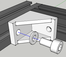
c)The aluminum profile are connected as below:
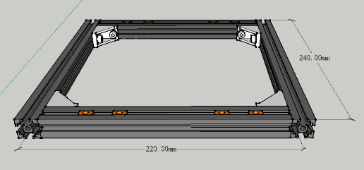
d)Final effect: If feel the assembling is smooth, please tighten the screw as possible, so as to keep it fix and stable.
e)Notice:
Try to assemble on flat place, working table is preferred.
2. Y Axis assemble
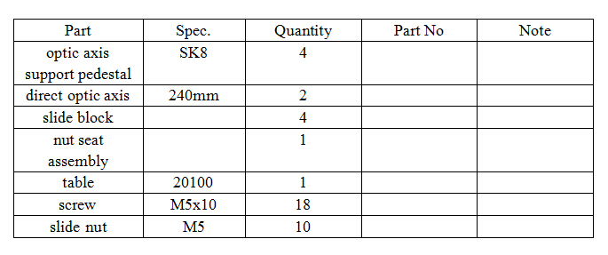
a)Part
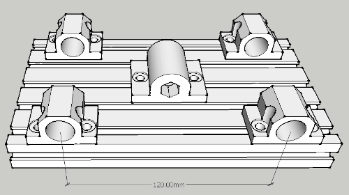
b)Direct optic axis pedestal assemble instruction: axis separation distance 120mm, which also could be adjusted as user’s mind. No need to tighten the screw too much, as it has to be adjusted slightly later.
e)Table assemble instruction view: No need to tighten the screw too much. The nut seat direction could be random. For slide block direction, please refer to below view.
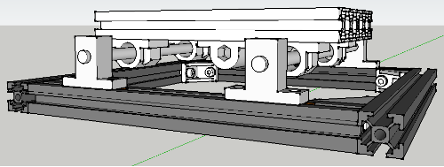
f)Final effect: The axis distance could be adjusted according to actual situation.
3.Y axis motor and lead screw assembly
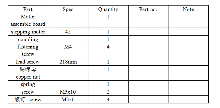
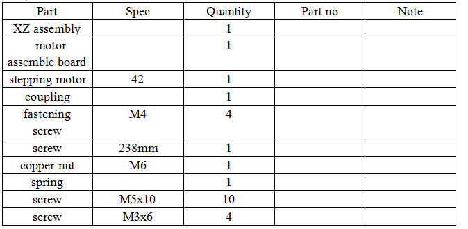
a)Part list
b)Motor assembly instruction: Please fix the coupling with the motor, as the motor shaft entering coupling for 12.5mm, then fix by the fastening screw. Fix the motor on motor assemble board, and fix the motor assemble board to the machine. Please note that no need to tighten the screw too much, for convenient adjust later.
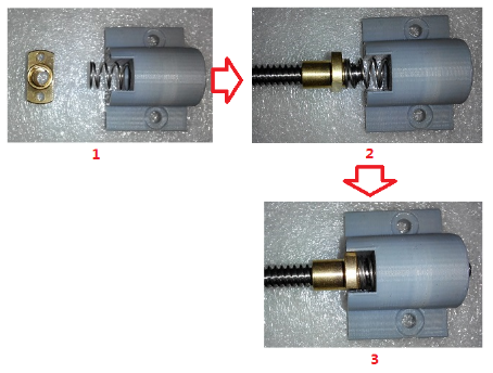
c)Screw assemble instruction:
d)Assemble screw and coupling
The screw and coupling connecting should be concentric, as the fastening screw should be side by side, and be tightened alternatively. After fix it, manually turn the screw with even speed, and try to feel if the resistance is even.
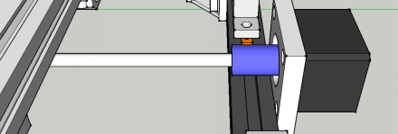
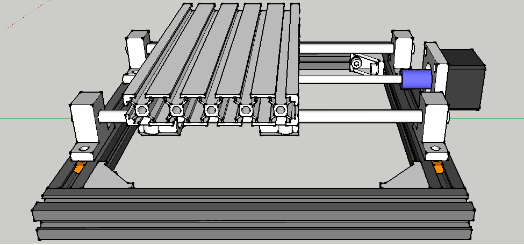
e)Please refer to final effect as below:
Portal frame assemble: a)Part
b)Final effect: Reserve one nut on the back, for the purpose to assemble the control board, please refer to below view.
4.X axis assemble
a)Part
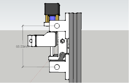
b)Install XZ assembly. Please refer to below view. Align the edge of optic axis supporting pedestal with top side of aluminum profile, with axis distance 68mm. The assembly requirement is the X axis could move evenly left and right.
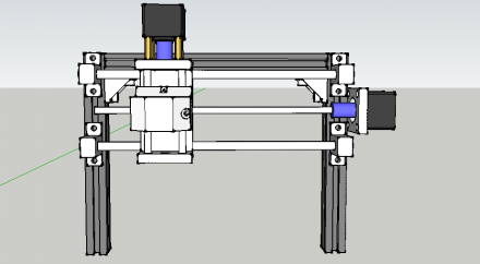
c)Please refer to final effect as below view.
5.Assembly
a)Part
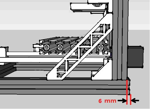
b) Please refer to below view for assembly: The distance between portal frame and pedestal tail should be 6mm, the reason for which is the spindle axis and Y axis could coincide.
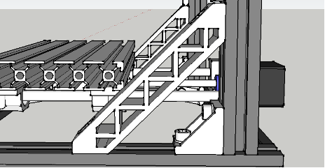
c)Assemble support
d)Install the assemble board of control board
Example Project
Assemble Video
Resources
- Control Software is used to control the machine
