Difference between revisions of "GPS Shield With SD Card Slot for Arduino V2.0 A"
Katherine.d (talk | contribs) (→Cautions) |
Katherine.d (talk | contribs) (→Pin definition and Rating) |
||
| Line 54: | Line 54: | ||
== Pin definition and Rating == | == Pin definition and Rating == | ||
| − | + | {| class="wikitable" border="1" | |
| − | + | ! width="200px" align="left"| Arduino PIN | |
| − | + | ! width="200px" align="left"| Description | |
| + | |- | ||
| + | | width="200px" align="left"| D0 | ||
| + | | width="200px" align="left"| Data | ||
| + | |- | ||
| + | | width="200px" align="left"| D1 | ||
| + | | width="200px" align="left"| Din | ||
| + | |- | ||
| + | | width="200px" align="left"| D2 | ||
| + | | width="200px" align="left"| - | ||
| + | |- | ||
| + | | width="200px" align="left"| D3 | ||
| + | | width="200px" align="left"| - | ||
| + | |- | ||
| + | | width="200px" align="left"| D4 | ||
| + | | width="200px" align="left"| - | ||
| + | |- | ||
| + | | width="200px" align="left"| D5 | ||
| + | | width="200px" align="left"| - | ||
| + | |- | ||
| + | | width="200px" align="left"| D6 | ||
| + | | width="200px" align="left"| - | ||
| + | |- | ||
| + | | width="200px" align="left"| D7 | ||
| + | | width="200px" align="left"| - | ||
| + | |- | ||
| + | | width="200px" align="left"| D8 | ||
| + | | width="200px" align="left"| - | ||
| + | |- | ||
| + | | width="200px" align="left"| D9 | ||
| + | | width="200px" align="left"| - | ||
| + | |- | ||
| + | | width="200px" align="left"| D10 | ||
| + | | width="200px" align="left"| CSN | ||
| + | |- | ||
| + | | width="200px" align="left"| D11 | ||
| + | | width="200px" align="left"| MOSI | ||
| + | |- | ||
| + | | width="200px" align="left"| D12 | ||
| + | | width="200px" align="left"| MISO | ||
| + | |- | ||
| + | | width="200px" align="left"| D13 | ||
| + | | width="200px" align="left"| SCK | ||
| + | |- | ||
| + | | width="200px" align="left"| A0 | ||
| + | | width="200px" align="left"| BREAKOUT | ||
| + | |- | ||
| + | | width="200px" align="left"| A1 | ||
| + | | width="200px" align="left"| BREAKOUT | ||
| + | |- | ||
| + | | width="200px" align="left"| A2 | ||
| + | | width="200px" align="left"| BREAKOUT | ||
| + | |- | ||
| + | | width="200px" align="left"| A3 | ||
| + | | width="200px" align="left"| BREAKOUT | ||
| + | |- | ||
| + | | width="200px" align="left"| A4 | ||
| + | | width="200px" align="left"| IIC_SDA | ||
| + | |- | ||
| + | | width="200px" align="left"| A5 | ||
| + | | width="200px" align="left"| IIC_SCL | ||
== Mechanic Dimensions == | == Mechanic Dimensions == | ||
Revision as of 08:29, 16 November 2012
Contents
Introduction
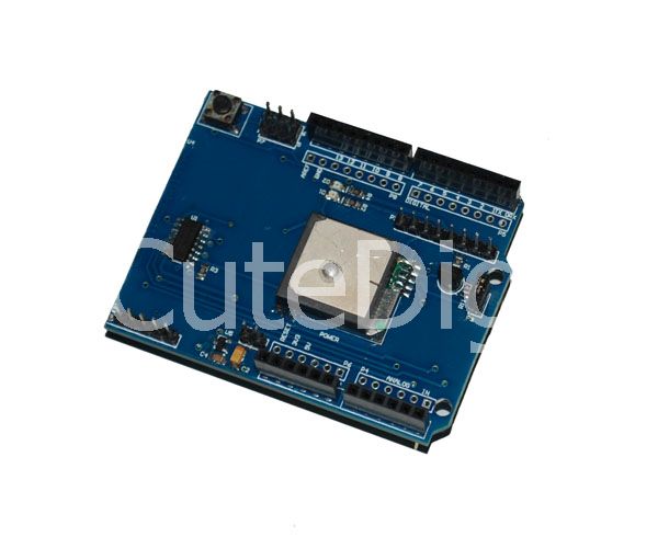
Arduino GPS shield is a GPS module breadout board designed for Global Positioning System receiver with SD interface. It is easy to use for recording the position data into SD card. 5V/3.3V compatible operation voltage level make it compatible with Arduino boards, leaf maple, IFlat32 and other arduino compatible boards.
Model:GPS_SD
Features
- With Micro SD interface
- Active antenna design with high receive sensitivity, compatible normal antenna
- Extremely fast time to first fix at low signal level
- UART interface
- Operation temperature: -40℃ ~ +85℃
Application Ideas
Cautions
The warnings and wrong operations possible cause dangerous.
Schematic
Arduino GPS Shield Schematic in PDF
Specification
| PCB | 55.88mm X 54.1mm X 1.6mm |
| Indicators | PWR |
| Power Supply | compatible with Arduino |
| Communication Protocol | UART |
| RoHS | Yes |
Pin definition and Rating
| Arduino PIN | Description |
|---|---|
| D0 | Data |
| D1 | Din |
| D2 | - |
| D3 | - |
| D4 | - |
| D5 | - |
| D6 | - |
| D7 | - |
| D8 | - |
| D9 | - |
| D10 | CSN |
| D11 | MOSI |
| D12 | MISO |
| D13 | SCK |
| A0 | BREAKOUT |
| A1 | BREAKOUT |
| A2 | BREAKOUT |
| A3 | BREAKOUT |
| A4 | IIC_SDA |
| A5 | IIC_SCL
Mechanic DimensionsUsageHardware InstallationProgrammingFAQPlease list your question here: SupportIf you have questions or other better design ideas, you can go to our forum to discuss or creat a ticket for your issue at linksprite support. ResourcesHow to buySee AlsoOther related products and resources. LicensingThis documentation is licensed under the Creative Commons Attribution-ShareAlike License 3.0 Source code and libraries are licensed under GPL/LGPL, see source code files for details. |
